Choose your operating system:
Windows
macOS
Linux


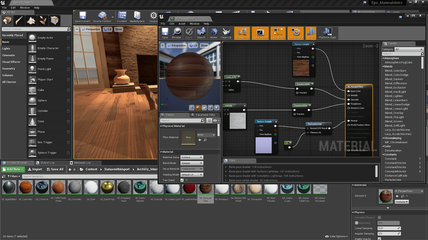


In this page, we take a look at the available inputs when making a Material. By feeding values (by way of constants, parameters, and textures) into these inputs, you can define just about any physical surface you can imagine.
Not all inputs are used with every combination of Blend Mode and Shading Model. As such, we will designate when each input is available for use, so that you know which inputs are used with each type of Material you create.
Inputs and Material Settings
Not all inputs will be useful for every type of Material you create. For instance, when developing a Light Function - a Material that is applied to a light - you can only use the Emissive Color input on the material and nothing else, since other inputs, such as Metallic or Roughness, would not be applicable. Because of this, it is important to know what type of Material you are creating before you start worrying too much about inputs. The three primary controlling properties in this are:
-
Blend Mode - This controls how your Material will blend in with the pixels behind it.
-
Shading Model - This defines how light is calculated for the surface of the Material.
-
Material Domain - This controls how the Material is intended to be used, such as whether it is meant to be part of a surface, a Light Function, or a Post Process Material.
Fortunately, Unreal Engine 4 removes the guess work for which inputs you need for a given type of Material. As you change these settings in the Material, you will notice that your available inputs will update, and inputs that you do not need will be disabled.
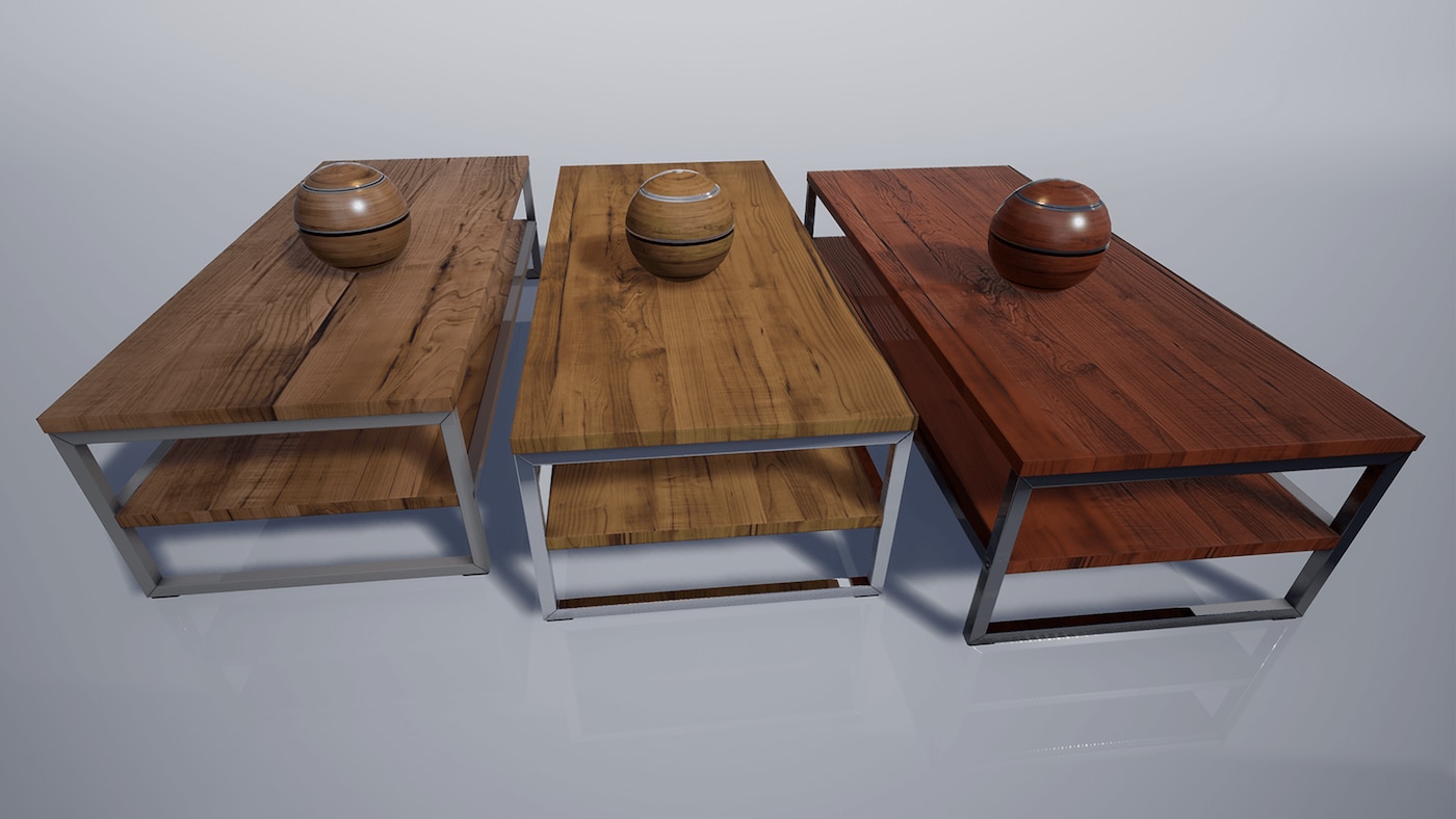
Base Color
Base Color defines the overall color of the Material, taking in a Vector3 (RGB) value where each channel is automatically clamped between 0 and 1.
If taken from the real world, this is the color when photographed using a polarizing filter (polarization removes the specular of nonmetals when aligned).

Metallic
The Metallic input controls how 'metal-like' your surface will be. Nonmetals have Metallic values of 0 and metals have Metallic values of 1. For pure surfaces, such as pure metal, pure stone, pure plastic, etc. this value will be 0 or 1, not anything in between. When creating hybrid surfaces like corroded, dusty, or rusty metals, you may find that you need some value between 0 and 1.

Specular
When you're editing a non-metallic surface material, there are times when you'll want to adjust its ability to reflect light, specifically, its Specular property. To update a Material's Specular, input a scalar value between 0 (non-reflective) and 1 (fully reflective). Note that a Material's default Specular value is 0.5.

Roughness
The Roughness input controls how rough or smooth a Material's surface is. Rough Materials scatter reflected light in more directions than smooth Materials, which controls how blurry or sharp a reflection is (or how broad or tight a specular highlight is). A Roughness of 0 (smooth) results in a mirror reflection and roughness of 1 (rough) results in a diffuse (or matte) surface.
Roughness is a property that will frequently be mapped on your objects in order to add the most physical variation to the surface.

Anisotropy and Tangent
The Anisotropy and Tangent inputs enable you to control how anisotropic the roughness of the material is and its light directionality. These two inputs are important for materials to recreate the anisotropic effect of something like brushed metal.

Without using the Anisotropic and Tangent inputs, materials have an isotropic response. This is also true when the anisotropic input has a value of 0.


The anisotropic response is controllable using a value between -1.0 and 1.0, where a value of 0 has no anisotropic effect.
Anisotropic materials are enabled by default but can be disabled using the console command
r.AnisotropicMaterials.
When enabled, anisotropy works with supported Gen5 platforms, and when scalabiltiy settings are High, Epic, or Cinematic.
Dragging the slider shows the anisotropic response positively increasing from 0.0 to 1.0.


Use the Tangent input to define light directionality with a texture or Vector expression.
Emissive Color
The Emissive Color input controls which parts of your Material will appear to glow because they are emitting light. Ideally, this will receive a masked texture (mostly black except in the areas that need to glow).
Values greater than 1 are allowed as HDR lighting is supported.

Opacity
The Opacity input is used when using the Translucent Blend Mode , typically for Translucent , Additive , and Modulated materials. You can input a value between 0 and 1, where:
-
0.0 represents completely transparent.
-
1.0 represents fully opaque.
Opaque and masked blend modes also use Opacity when using one of the subsurface shading models.

Opacity is mostly used for Translucent , Additive , and Modulated Materials .
Opacity Mask
Opacity Mask is similar to Opacity, but is only available when using the Masked Blend Mode. As with Opacity, this takes in a value between 0.0 and 1.0, but unlike Opacity, varying shades of gray are not seen in the result. When in Masked mode, a Material is either completely visible or completely invisible. This makes it a perfect solution when you need Materials that define complex solid surfaces such as wire mesh, chain link fences, and so on. The opaque portions will still respect lighting.
You can use the Opacity Mask Clip Value property on the base Material node to control the point where clipping takes place. See the Masked Blend Mode documentation for more details.

Normal
The Normal input takes in a normal map, which is used to provide significant physical detail to the surface by perturbing the "normal," or facing direction, of each individual pixel.

In the image above , both weapons are using the same Static Mesh. The lower one exhibits a highly detailed normal map, which provides additional detail, giving the illusion that the surface contains many more polygons than are actually being rendered. Typically, normal maps are often created from high-resolution modeling packages.

World Position Offset
The World Position Offset input allows for the vertices of a mesh to be manipulated in world space by the Material. This is useful for making objects move, change shape, rotate, and a variety of other effects. This is useful for things like ambient animation.
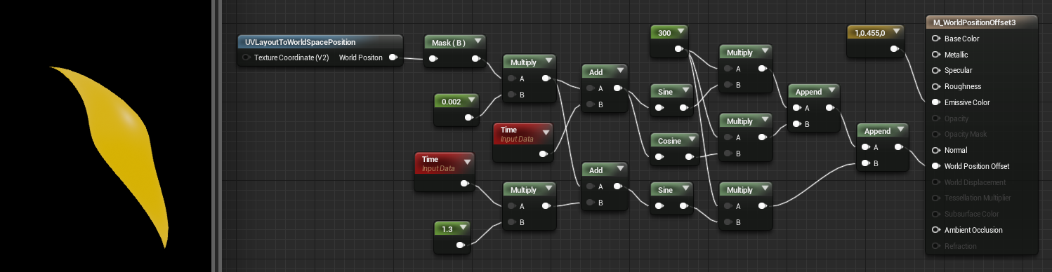
Click image for full size.
The above network will cause your object to simultaneously spiral and wave up and down, like it is dancing!
When using World Position Offset to expand your object beyond its original bounds, keep in mind that the renderer still uses those original bounds. This means that you may see culling and shadowing errors. You may go into the properties of a mesh and set its Scale Bounds property to compensate, though this has a draw on performance and may lead to shadowing errors.
World Displacement & Tessellation Multiplier
World Displacement works very much like World Position Offset, but it uses Tessellation vertices rather than the base vertices of the mesh. In order for this to be enabled, the Tessellation property on the Material must be set to something other than None .
Tessellation Multiplier controls the amount tessellation along the surface, allowing more detail to be added where needed. As with World Displacement, for this to be enabled, the Tessellation property must be set to something other than None .

When using World Displacement to expand your object beyond its original bounds, keep in mind that the renderer still uses those original bounds. This means that you may see culling and shadowing errors. To address these issues, you can edit the mesh's Scale Bounds property, although your edits could result in a performance drain, potentially leading to other errors (such as improper shadowing).
Subsurface Color
The Subsurface Color input is only enabled when the Shading Model property is set to Subsurface. This input allows you to add a color to your Material to simulate shifts in color when light passes through the surface. For instance, human characters might have a red subsurface color on their skin to simulate blood beneath the surface.

Hair
The Hair Shading Model is used to better simulate the translucent nature of hair and approximates how light passes through it since hair is not a perfect cylinder. Also, because each strand of hair is generally pointing in a different direction, the specular highlight is not unified and is instead independently placed based on the direction that the hair is pointing.

The Hair Shading Model opens up three inputs on the Main material node:
-
Scatter: This input controls the amount of light scatter that is allowed to happen through the hair.
-
Tangent: This input replaces the Normal input and is used to control the normal direction along the U and V texture coordinates.
-
Backlit: This input controls the amount of backlighting that affects this hair material.
For an example of hair set up using this Shading Model, see Digital Humans documentation and sample project available on the Epic Games Launcher in the Learn tab.
Cloth
The Cloth Shading Model can be used to better simulate cloth-like materials that have a thin layer of fuzz over the surface of the Material.

The Cloth Shading Model opens up two inputs on the Main Material node:
-
Fuzz Color: This input enables you to add color to your Material to simulate shifts in color when light passes through the surface.
-
Cloth: This input enables you to control the strength of the Fuzz Color as a mask. A value of 0 indicates no fuzz color contribution to the Base Color, whereas a value of 1 blends fully over the Base Color.
Eye
This is an advanced shading model that is highly technical and has very strong dependencies between shader code, the Material, the shape of the geometry and its UV layout. Instead, we recommend using our Digital Humans sample project as a starting point when developing your own eye assets or migrating them from this project.
The Eye Shading Model is designed to simulate that of an eye's surface.

The Eye Material Instance below has been set up to expose artistic cotnrol over the different biological parts of the eye shader that can be found in the Digital Humans sample project.
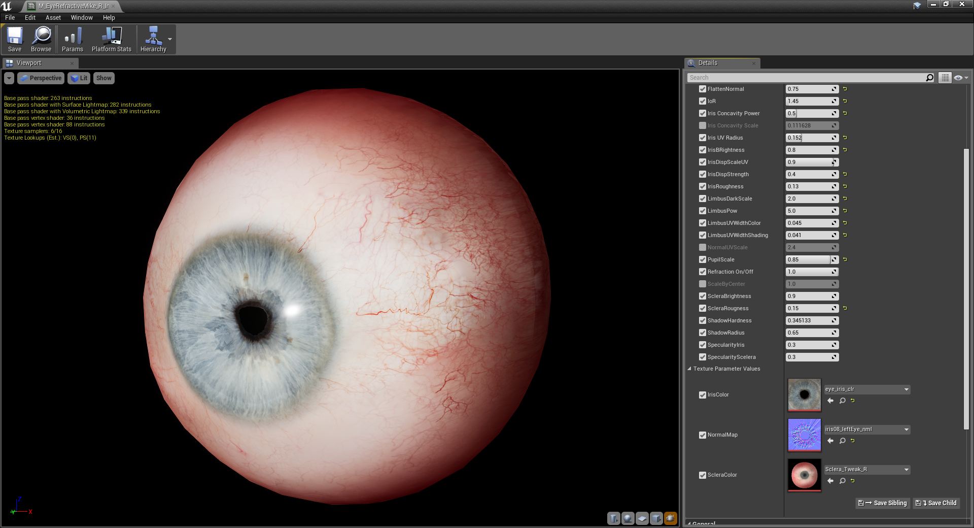
Click image for full size.
The Eye Shading Model adds two additional inputs to the Main Material node:
-
Iris Mask: This helps control the index of refraction and depth of the iris.
In the Material M_EyeRefractive in the Digital Humans sample project, see the IOR and Depth Scale parameters.
-
Iris Distance: This controls the concavity of the refracted iris.
In the Material M_EyeRefractive in the Digital Humans sample project, see the Iris Concavity Scale and Iris Concavity Power parameters.
Clear Coat
The Clear Coat Shading Model can be used to better simulate multilayer materials that have a thin translucent layer of film over the surface of the Material. In addition to this, the Clear Coat Shading Model can also be used with either metal or nonmetal surfaces. In fact, it was specifically designed to model this second class of smooth colored films over a non-colored metal. Some examples of Clear Coat Materials includes acrylic or lacquer clear coats, and colored films over metals such as soda cans or car paint.

The Clear Coat Shading Model opens up two new Material inputs on the Main Material node.
-
Clear Coat : Amount of clear coat layer, 0 acts like the standard shading model, 1 is the full clear coat model. This is useful for masking.
-
Clear Coat Roughness : Roughness for the clear coat layer. Our approximation is accurate for small values. Very rough clear coat layers are supported but will not be very accurate compared to their real world counterparts.
Ambient Occlusion
The Ambient Occlusion input is used to help simulate the self-shadowing that happens within crevices of a surface. Generally, this input will be connected to an ambient occlusin texture map of some type, which is often created within 3D modeling packages such as Maya, 3ds Max, or ZBrush, or photo editing software such as Photoshop.
Note that this input relies on light sources using Static or Stationary mobility to generate built lighting. This material input is silently ignored when its material is used in conjunction with any Movable light sources.
Refraction
The Refraction input takes in a texture or value that simulates the index of refraction of the surface. This is useful for things like glass and water, which refract light that passes through them.

|
Common Indices of Refraction |
|
|---|---|
|
Air |
1.00 |
|
Water |
1.33 |
|
Ice |
1.31 |
|
Glass |
1.52 |
|
Diamond |
2.42 |
Pixel Depth Offset
The Pixel Depth Offset can be used to control pixel depth in the shader graph using logic you set up. This enables you to create your own logic to blend or fade objects based on their scene depth.

In this comparison, using Pixel Depth Offset with the DitherTemporalAA Material Function enables us to set an "offset" value that blends the ground with the object intersecting it using a stipple pattern texture.


Shading Model
This input requires that the Shading Model be set to From Material Expression in the Material Details panel.
The Shading Models input enables you to use logic in your Material Grpah to select from a list of available shading models to use for part of your material. For example, it can be useful when you have a single object that needs to use multiple shading models, like Clear Coat and Default Lit. This can reduce the number of materials required, in turn, saving performance and draw calls. All of this can be driven by logic in your material using the Shading Model expression node and some texture masks.
The following is a simple example using an If expression to choose between shading models.
![]()
Using this example, when A is greater than B, the resulting shading model is Default Lit . When A is less or equal to B, a texture mask is used to display Default Lit and Clear Coat shading models on parts of the mesh.
![]()
![]()
For more information and examples of this inputs usage, see the From Material Expressions page.