Choose your operating system:
Windows
macOS
Linux

When creating assets for your game, you will often go through the process of setting up a UV that is laid out for your textures. If your project intends to use any form of baked lighting (static or stationary), you will also need to set up a UV channel that stores lighting information. This UV is called a Lightmap UV , which is similar to a texture UV in that it consists of laid-out UV charts (or UV islands) that are unique to each static mesh except this particular UV is used to store baked lighting and shadow information. The process of lightmapping is one of the more challenging areas of environment art creation because, unlike texture UVs, each face of the model needs to have its own unique space on the lightmap with no overlapping faces, and UV charts need to ensure that there is enough padding (or spacing) between them to avoid artifacts.
Lightmaps are only required when a static mesh will be lit using any form of baked (or precomputed) lighting. If your game or project only uses dynamic lighting, there is no need to set up lightmaps for each static mesh.
Creating a Lightmap
There are two ways you can create a lightmap:
-
Using Unreal Engine 4's Lightmap Auto-Generation tool
-
Creating a custom one with UV editing tools
Auto-Generating Lightmap UVs
Creating custom lightmap UVs can be a time-consuming process, especially if you have projects requiring thousands or ten of thousands of assets. An auto-generated lightmap can be a quick way to pack a lightmap UV to save you a significant time investment of manually setting one up and padding it correctly. We've adopted this process into our own workflow here at Epic.
When importing your own assets, a lightmap UV will be generated for you automatically (unless disabled) in the
FBX Import Options
window.

A lightmap will be automatically generated based on the UV for the texture layout (UV channel 0). The generated lightmap UV repacks the islands so that they meet the requirements of a good lightmap with no errors: no overlapping or wrapping islands, and enough padding between islands to limit artifacts based on the targeted lightmap resolution.
Once a lightmap UV has been generated for a static mesh, it can be adjusted in the Static Mesh Editor, using the lightmap generation settings in the Details panel Build Settings , but there is no requirement to ever touch these settings once the lightmap UV has been generated.

These settings can be used at any time to generate a lightmap UV or repack existing ones. The tool uses a repacking algorithm to generate the lightmap based on a Source Lightmap Index (or UV channel) and then stores it in a new specified by the Destination Lightmap Index . The algorithm repacks the UV charts from the specified source lightmap index but does not cut or split them in the process. Keep this in mind when creating lightmap UVs and by doing a little bit of upfront work in your modeling software or UV editing software, you can get a good result by splitting the UV charts before import into UE4.
For additional information, see Generating Lightmap UVs .
Custom Lightmap UVs
For the majority of static meshes that you import into UE4, you'll be able to use an auto-generated lightmap UV because a good result can be achieved with minimal effort. However, for those times when it's not possible to adequately use an auto-generated UV, you'll want to create a custom lightmap unwrap in your modeling software or UV editing tool.
Depending on the capabilities of your UV editing tools and the type of asset you're creating, you may find that a custom lightmap is the ideal choice since it may require more attention to detail than other assets. A lot of UV editing tools, like the one pictured below from Autodesk 3ds Max have a range of features that enable you to easily flatten, reshape, connect, and break apart UV charts in ways that make sense. These are options that are not available with UE4's lightmap generation.

Autodesk 3ds Max UV Editing Tools.
Later parts of this page will cover the basics unwrapping UVs to get specific results and this is a process that can be combined with auto-generate lightmaps. If you'd like to jump ahead, you can see the Contiguous UVs and Padding section of this page.
Texture UV versus Lightmap UV
Setting up a texture UV often requires a different approach to laying out the UV charts to get the best result than how you would for lightmap UV. Lightmaps must be laid out flat without any overlapping areas and they need enough padding between each UV chart to ensure that there isn't any light leaking. Setting up a texture UV doesn't have these stipulations because it only matters how you want the texture mapped to those UV charts. It's acceptable for them to have islands that are overlapping or even wrapping, because you can have tiling textures or ones assigned to different parts of the geometry.
For example, the building facade below has four sides that have the same texture mapped to its different faces. Instead of using UV space for each side, a single texture has been created and each side's UV charts have been laid on top of one another. This enables space to be used efficiently for a single texture that is mapped to all faces without having to use a higher resolution due to less texel density.
When the lightmap is laid out (right), all faces are represented with their own UV space so that a proper light bake can be generated. Some parts have been separated and are given enough padding between the other charts to ensure fewer artifacts or light leaks.

Texture UV Layout

Lightmap UV Layout
Contiguous UVs and Padding
One approach to setting up lightmapping UVs is to have contiguous (or connected) groupings of the geometry. To generate a smooth lighting result, it's ideal to connect faces in ways that make sense to represent the geometry.
For example, the UV charts below have connected all the front and side faces of the geometry into a single UV chart and the top has been separated into its own island.

UV Charts for the static mesh geometry.
Once unwrapped, it's necessary to include a minimum amount of padding between UV charts to prevent light and shadow bleed artifacts. A minimum of four texels is usually required to avoid all bleeding artifacts since DXT texture compression operates on 4x4 texel blocks.
If you are setting up a custom lightmap for padding, use the following equation to determine the proper texel spacing for your grid:
1 / Target Lightmap Texture Resolution = Texel Grid SpacingExample of the formula above using a resolution of 64 :
1 / 62 = 0.0161290323UE4 uses a pixel for padding meaning that we need to subtract one from each side when trying to find out snapping grid to manually snap UV charts to the grid. Using the auto-generated lightmap UVs will pack them with the appropriate padding.

-
Wasted UV Padding
-
Necessary UV Padding
The edges of the lightmap UV do not need additional padding because Lightmass already pads around the edges of the lightmap to prevent any sort of light and shadow bleeding when combining the lightmap texture atlas for the level. This leads to unnecessary padding and wasted UV space.
Using the UV space efficiently can require you to force some UVs together with brute force and scaling to fit them within the UV space.

(From left to right) Lighting only view in Unreal Engine; static mesh with texture; texture UV layout, lightmap UV layout.
It's more important that we have a clean contiguous surface without interruption for the lighting result than to worry about 1:1 scaling. A lightmap that has a 1:7 scaled ratio whereby it has twice the coverage will produce a better result even if the islands are non-uniformly scaled. Areas that are too thin but maintain a 1:1 ratio will not light correctly because it cannot capture a good result. Another key takeaway from this example is that the negative interior cuts have been separated (highlighted red) to prevent them from sharing light and shadow information for the contiguous UV charts where a smooth lighting result is important.
Lightmap UV Examples
The following examples explore custom lightmap UV layouts for simple, complex, and organically structured geometry. These can give you an idea of how to approach and maintain a smooth lighting result.
Simple Object
This building facade represents a simple modular piece that is a good example of a contiguous geometry that when unwrapped mirrors its low-poly geometry.
Texture UV Layout
Lightmap UV Layout
Using contiguous faces make it much easier to maximize coverage in the UV space for better light bakes at lower lightmap resolutions with a nearly perfect lightmap. Notice that there are no seams and no subtle dark lines caused by split UV charts.

Click image for full size.
Complex Object
For designs that do not adhere to any of the rules of thumb for contiguous UVs, like ones that have a lot of geometry or negative space with few elements, you will need to split the UV charts and add much more padding to prevent artifacts.
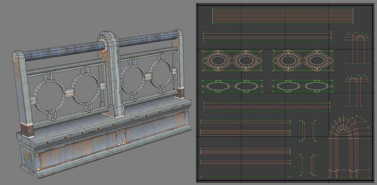
Static mesh and lightmap UV layout
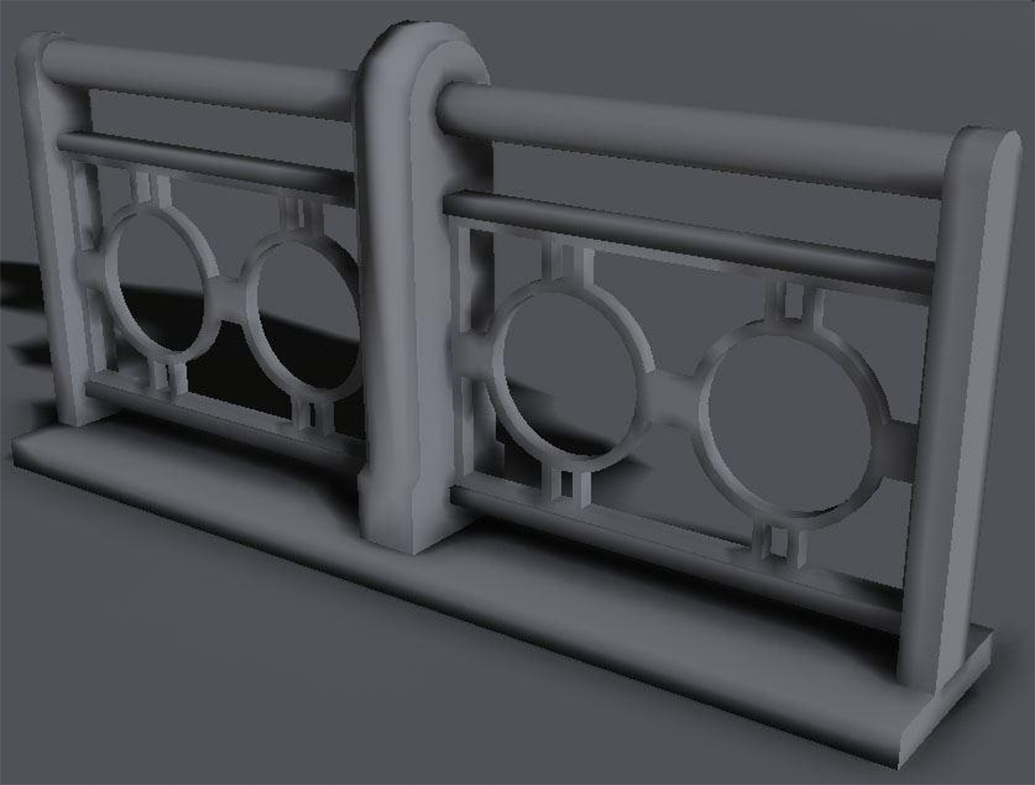
Light bake result
The railings lightmap shows some distortion on the vertical pieces that hold the rail together (middle image, right side). The two sides and middle section of those pieces were forced together. Even though it has distortion in the UV, it still has enough coverage to generate a good result.
The interiors of the circular pieces on the railing have been split for the front and the back sides into their own contiguous islands. The side that will be visible to the player has the inner and outer faces grouped so that three-quarters of those areas have smooth lighting. The back side of the railing is its own island since it's most likely not something that would be easily visible in the level. Instead, focusing on the majority that is visible to players is most important to have a good result for.
Sometimes, you may have complex geometry that works against what works best for a Lightmap UV. In addition to the medium-sized asset, this one has a lot of negative space, which only adds to its complexity.

Static mesh and lightmap UV layout
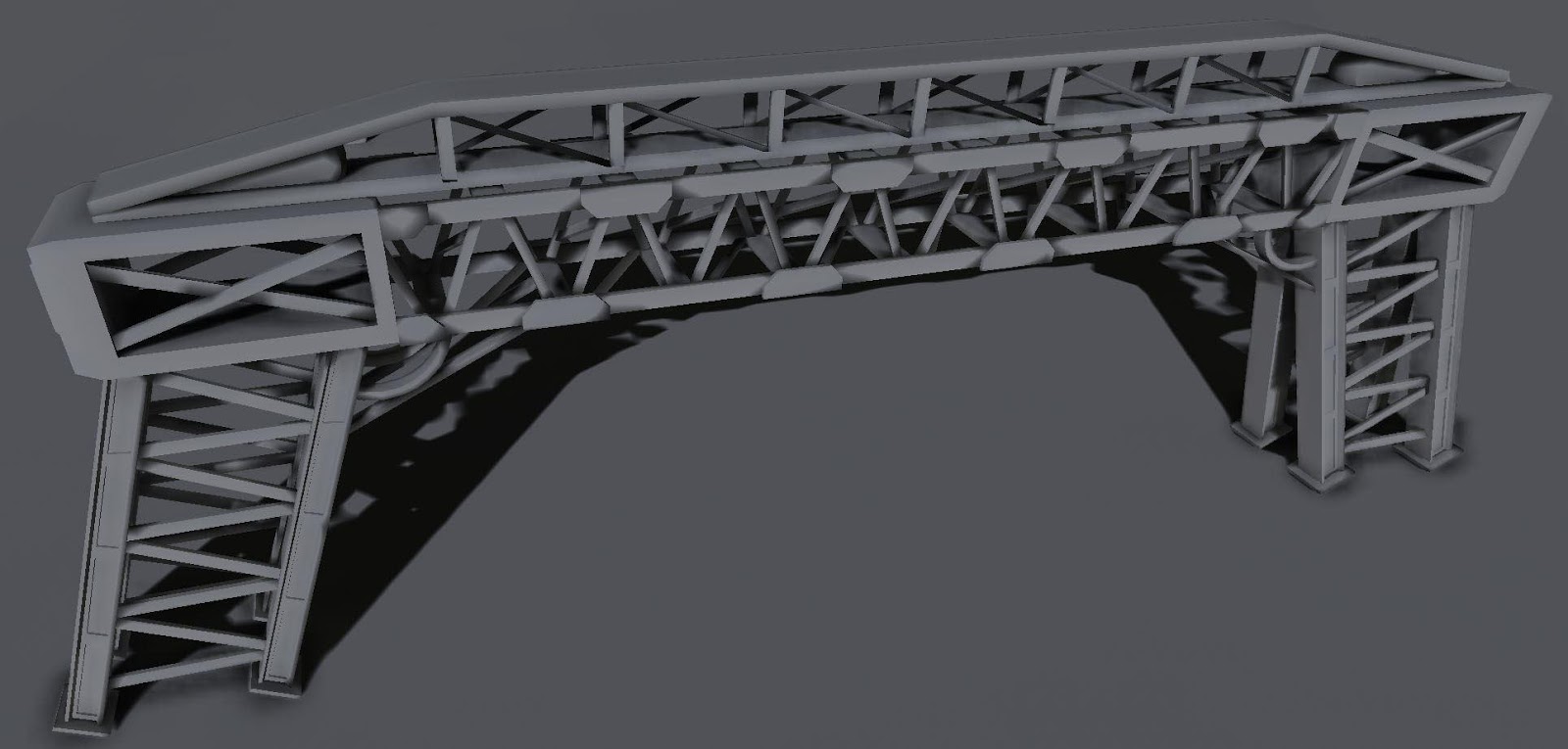
Light bake result
When there are so many separate elements, there is a potential for a lot of wasted UV space due to padding. In this instance, there is no choice but to use a higher lightmap resolution to ensure that quality is maintained. By using a little forethought, this example planned to use a higher lightmap resolution by combining UV charts that made sense and also knowing that it would still not look perfect. There will be some bleed but not so much that it would ruin the lighting result.
Depending on your memory budget, you could use a higher lightmap resolution to reduce some artifacts, but it's always better to use as low a resolution as possible for performance and optimization. Also, keep in mind that a good material with an interesting diffuse and normal texture can hide some lightmap issues.
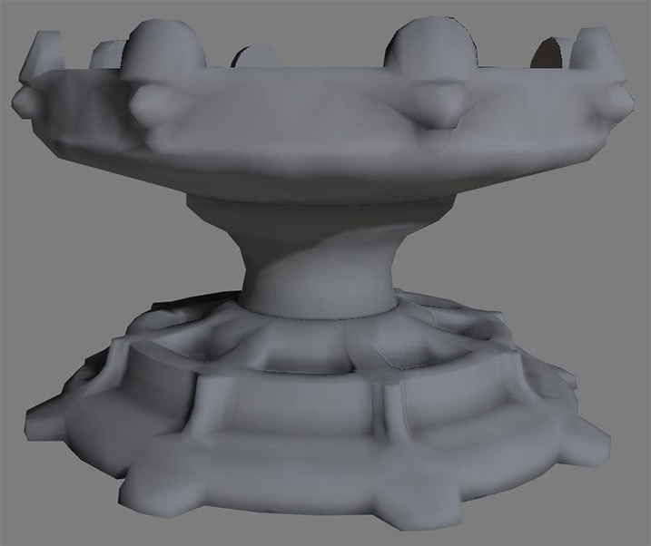
Organic Object
For geometry that has a lot of rounded shapes or that is more organic in design, it's better to project the surface flat and relax the UVs as needed.
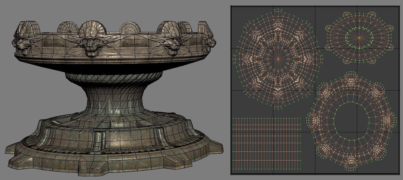
Static mesh lightmap UV layout
Baked Lighting Result
For organic shapes, look at how the geometry can be broken apart in a way that makes sense, like splitting UV charts at places that would naturally work. The biggest concern when doing this is that any edge split will break the smoothness of the lighting result. So, in the case of this fountain, breaking the top of the fountain into its top and bottom halves, the center being its own, and the bottom base as its own island make the most sense to reduce visible seams in the light bake. A good rule-of-thumb is to split your lightmap UVs at sections where there are deep recesses or crevices.
The UV chart for the center column doesn't look like its mesh, instead, it's been straightened out to use the UV space more efficiently. For a lightmap UV, this is perfectly acceptable to enable a nice, smooth lighting result.
The Importance of Lightmap Resolution
An effective lightmap will fill the majority of the UV space as efficiently as possible in order to use the lowest resolution that obtains a good lighting result. Most lightmapping issues can be mitigated by using the UV space to maximize coverage while maintaining enough padding between the UV charts.
If your project is built for desktop platforms, they can typically afford to use higher resolutions since they have a larger memory budget to pull from. However, for consoles and mobile platforms, memory budgets need to be tightly controlled. It's common to sacrifice some lightmap resolution quality to stay within budget.
Depending on the geometry and its complexity, it may be helpful to break the mesh into smaller pieces so that each can have a unique lightmap with good coverage and use a lower lightmap resolution while doing so.
Inspecting Lightmaps and Settings
Static Mesh Editor
The Static Mesh Editor enables you to inspect any UVs attached to your Static Mesh, generate your own Lightmap UVs , set the resolution of the lightmap texture for this mesh, and more.
Enabling the UV Overlay
Use the UV dropdown in the toolbar to select a UV channel to display.

Once selected, the UV channel displays an overlay in the Static Mesh Editor Viewport.

The currently displayed UV channel is indicated above the overlay.

Setting the Lightmap Coordinate Index
The Lightmap Coordinate Index specifies which UV channel should be used for this static mesh when Lightmass generates a lightmap texture during a lighting build.
In the Static Mesh Editor General Settings section, locate the Lightmap Coordinate Index .

UE4 will attempt to assign the proper UV channel where possible when importing a static mesh that currently has a lightmap channel (UV Channel 1) or if a lightmap is generated during import. However, if you generate a lightmap UV after import for a static mesh that did not already have one, you'll need to manually assign the correct UV Channel to the Lightmap Coordinate Index.
Setting the Lightmap Resolution
The Lightmap Resolution enables you to set the default texture resolution for the baked light and shadow texture generated by Lightmass during a lighting build. This resolution will be used for all instances of this Static Mesh placed in a level.
In the Static Mesh Editor General Settings section, locate the Lightmap Resolution .

You can also override a static mesh's lightmap resolution in any level by enabling Overridden Light Map Res and plugging in a resolution size. This setting overrides this particular instance of the Static Mesh.

Setting Light Map Resolution or Overridden Light Map Res lower than the Min Lightmap Resolution used for a generated Lightmap UV will cause seams and potential light leaks once lighting is built. The Min Lightmap Resolution should be the lowest resolution you ever intend to set for this Static Mesh to ensure that enough padding is maintained between UV Charts.
Level Viewport
The Level viewport enables you to use different view modes to inspect your lighting builds and lightmap resolution densities relative to other Static Meshes. These view modes help you inspect the final results as well as troubleshoot lightmap and lighting build issues.
Using the Lightmap Density View Mode
The Lightmap Density view mode enables you to visualize the density of the assigned lightmaps resolution with a checkered grid relative to other Static Mesh Actors in the level based on an "ideal" (or max) density setting. It's important to have an even density across your scene to get consistent lighting when using baked lighting.

A scene from Epic's Infiltrator demonstrating the Lightmap Density view mode.
Enable this view by using the Level viewport to select View Modes > Optimization Viewmodes > Lightmap Density .

Once enabled, a color grid will overlay all Static Meshes in the scene based on their current Lightmap Resolution.
The following density colors indicate how the ideal lightmap resolution for the level relates to the lightmap resolution set for the static meshes in the level.
|
|
|
|
|---|---|---|
|
Less than ideal texel density |
Ideal texel density |
Max or greater than ideal texel density |


Note that any Static Mesh with its mobility set to Movable will display Brown in the Lightmap Density view mode since it doesn't require a lightmap UV or need to be optimized within this regard.
The default density is an average one to get you started. Depending on your game's texture budget, you may need to adjust the color ranges to be more strict or loose to make this view mode useful to your project. Use the Lightmap Density Rendering Options found in the main toolbar under the Build > Lighting Info to set them.

|
Property |
Description |
|---|---|
|
Ideal Density |
Sets the ideal density at which texel density should be for objects in the scene. The ideal texel density is green. |
|
Maximum Density |
Sets the maximum density at which texel density is considered too dense for the scene. The texel density is red. |
|
Color Scale |
Scales the color for the scene when using Lightmap Density view mode. |
|
Grayscale Scale |
Scales the brightness level of the grayscale factor for the scene based on the Ideal and Maximum density values. |
|
Render Grayscale |
Enables grayscale to be used for the lightmap density view mode. |
Lighting Only View Mode
The Lighting Only view mode is useful to inspect lighting in your scene without material texture information. This is extremely useful when looking at the light build result.

Use this view mode with Error Coloring to visualize lightmap errors in your scene resulting from overlapping or wrapping UVs.
World Settings
The World Settings panel contains settings specific to the level currently loaded, it includes some additional settings specific to lightmaps, like choosing whether they should be compressed to save memory, setting the maximum size of the packed texture atlas that stores the lightmaps, and access to the packed lightmap textures generated for the level.

Compress Lightmaps
By default, UE4 already compresses generated lightmap textures for optimization. When the Compress Lightmaps checkbox is unchecked, the packed lightmap texture atlas will not use compression. It will increase memory usage significantly (by four times) when doing so, but it can reduce artifacts caused by compression algorithms.
For surfaces that do not use a normal map, compression artifacts can be visible for smaller lightmaps packed into the texture atlas. By using good textures and normal maps, the baked lighting result is improved. For some problematic lightmap UVs where you're increasing lightmap resolution, keep in mind that re-working the UV charts to have additional coverage within the UV space can improve these types of compression artifacts.
Directly Lit Areas
In directly lit areas with high contrast, compression artifacts may be easier to spot. With compression disabled, the lightmap result is smoother, without the blotchiness but at a much higher cost.


Indirectly Lit Areas
In indirectly lit areas, compression artifacts are less noticeable. While the result is smoother when compression is disabled, it's less likely to be noticed when textures and normal maps are applied.


Directly Lit Areas with Increased Lightmap Resolution
The lightmap resolution of the trim mesh at the base of the wall (centered between the columns against the floor) has been increased to demonstrate that similar results can be achieved by simply increasing the lightmap resolution rather than disabling compression. By doubling the original lightmap resolution, the majority of artifacts have been eliminated and the texture memory usage is minimal to non-existent for this small of a change.


Packed Light and Shadow Map Texture Size
When lightmaps are generated for the level for individual Actors, they will be packed and stored into multiple texture atlas'. Loading individual lightmap textures per-Actor is not very efficient and would increase the GPU workload to load and unload them continuously.

The number of Static Mesh Actors used in a level and their lightmap resolution will determine the number of texture atlas' that will be used. Larger lightmap resolutions increase the amount of space they use in the atlas. The size of the texture atlas can be adjusted by using a power of two (512, 1024, 2048, or 4096) value for the setting
Packed Light and Shadow map Texture Size
.

Troubleshooting and Optimization
Error Coloring
Error Coloring enables any warnings that appear in the Message Log under Map Check to be visualized after a lighting build by overlaying a color in the lightmap where the error is occurring.

When
Use Error Coloring
is enabled, the
Lighting Quality
must be set to
Medium
or
Preview
to visualize the results.

Using the Lighting Only view mode can make it easier to look for and find these types of issues.
Overlapping Lightmap UVs
An Overlapping Lightmap UV warning indicates that the UV charts are overlapping another part of the geometry within the UV space of the lightmap. All UVs must have their own space in the UV when being used for a Lightmap. The error coloring overlays Orange for any of these UV charts. Note that Texture UVs do not have to adhere to this.

Click image for full size.


Wrapping UVs
A Wrapping UV warning indicates that the UV charts are outside of the 0-1 UV space. The error coloring overlays Green for any of these UV charts.

Click image for full size.


Statistics Window
The Statistics window contains a lot of useful data for lighting, textures, and primitives that are in the currently loaded level(s). A lot of the data here requires a lighting build first to be useful.
To open the Statistics window, use the file menu to select
Edit > Statistics
.

Click image for full size.
Use the dropdown menu in the upper left to select the type of data you want displayed.

Lighting Build Info
The Lighting Build Info shows a sorted list of Actors in the currently loaded level(s) and how it took to compute lighting for each of them. This list can help you to track down problematic meshes that may be taking a long time to compute lighting for. For example, a high lightmap resolution or number of lights in the scene interacting with an Actor can contribute to the time it takes to compute lighting for it.
Click image for full size.
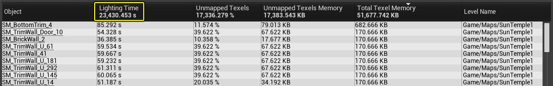
Static Mesh Lighting Info
The Static Mesh Lighting info shows a sorted list of Actors in your currently loaded level(s) and information about its lightmap. This list can help you quickly identify the lightmap resolutions of Actors and the texture memory they'll use.

Click image for full size.