Choose your operating system:
Windows
macOS
Linux
The Audio Modulation system provides control over common floating-point audio parameters from the Blueprint and Component systems. The system includes a better, more intuitive and dynamic subset of features for mixing audio sources, and for dynamically controlling and parameterizing audio properties than Unreal Engine has had in prior versions.
The system:
-
Exposes a generic, flexible, decoupled, generic parameter modulation and mix system.
-
Establishes a more robust set of tools for auditioning and debugging a game's mix.
-
Provides an API that can be easily extended and used for further modulation of sources, effects, submixes, and various other audio types via plugins.
Audio Modulation is a powerful way to modulate virtually any float- or buffer-based parameter within the Unreal Audio Engine. In the most basic form of modulation, a user can connect a Modulation Source to a Modulation Destination . If no source is referenced, a default value , as provided by a Modulation Parameter , is mixed together with the value supplied as the default Modulation Destination value (see Modulation Sources and Mix Stages ). This scenario can be thought of as plugging a traditional hardware patch cable into a modulation input, with the output end connected to a known quantity, such as a ground or voltage source.
Enabling Audio Modulation
All modulation features are encapsulated in the Audio Modulation plugin, and implement a lightweight, engine-side API.

To enable the Audio Modulation plugin, go to Edit > Plugin , click Audio in the left panel, then check Enabled for Audio Modulation.
Enabling the plugin, then restarting the editor or rebuilding in Visual Studio enables Unreal's native implementation of the Audio Modulation system.
Modulation Values
All modulation values can be transformed between two value spaces, the unit value space and the normalized value space. The unit space is displayed and provided as a means of convenience in the editor, while the normalized space provides a uniform way of passing and mixing bus values. All modulation values map to a normalized [0.0f, 1.0f] range. In a similar way to how a hardware synthesizer might use a control voltage (CV) as a standard for passing a value from a source to a destination, the Modulation System uses Control Buses that always contain values within the normalized float range.
Taking the case of Volume, the unit space may be the range between -60 dB (threshold of silence—which is configurable via the Modulation Parameter ) and 0 dB (full volume), where the normalized values map logarithmically to the normalized space of 0.0f and 1.0f. Semitones is another example where a minimum and maximum value of +/- 12 in unit space can be configured in its respective Modulation Parameter settings. The normalized space always maps between 0.0f and 1.0f. In the most basic case, the unit and value space are identical—namely, all unit values correspond to the same normalized value between 0.0f and 1.0f.
Modulation Parameters
Modulation parameters provide context for how a value associated with a bus, bus mix, destination, and patch is displayed, mixed, and transformed to and from unit and normalized (unitless) [0.0, 1.0] values. They include a Unit Display Name property that dictates how to display units to all modulators referencing them, and a default parameter value. This value should be set to a value that results in no change to an input when a modulator referencing this parameter is mixed with another. (Mathematically, the value should be selected so that the mix function is effectively reduced to an Identity Function when set as an input).
For example, the Volume Default Modulation Parameter has a default value of 1.0f in normalized space (0 dB in unit space) and when mixed multiplicatively, this leads to no change at the output (meaning that mixing the input with this value results in the same value on the output).

The Volume Default Parameter Value results in no change at output when mixed multiplicatively.
Similarly, pitch has a default value of 0.5f in normalized space (0.0 semitones in unit space) as adding 0 semitones results in the same value as the value it is mixed with.
A Parameter Note for Developers:
In code, the base class
USoundModulationParameter
can be inherited from, and can provide overloaded functions used to mix values (
GetMixFunction
) as well as transform values to and from unit and normalized space (
GetUnitConversionFunction
and
GetNormalizedConversionFunction
respectively).
GetMixFunction
returns an
FModulationMixFunction
, which is passed with a set of two float buffers—an
InValueBuffer
to mix into an
OutValueBuffer
, where the
InValueBuffer
contains values in normalized space.
Modulation Destinations
A Modulation Destination (
FModulationDestination
, found in the engine module) is any endpoint that provides a float value to an audio source or effect, and can be modulated by a referenced modulating source.

1) The base value that can be modulated; 2) Check to enable or disable modulation; 3) The source object to be modulated.
Modulation Destinations can be found on properties in a Submix Effect Preset, Source Effect Preset, or sound type (such as SoundWaves, SoundCues, and anything that generally inherits from the SoundBase Class). Standard Modulation Destinations for modulation on sound types include Volume, Pitch, Highpass, and Lowpass.
A Modulation Destination includes three basic properties:
-
A base value (in units) that can be modulated.
-
A boolean indicating whether or not modulation is enabled.
-
A modulation source object , which can be a Control Bus, Modulation Generator, or Modulation Patch.
Modulator Sources and Mix Stages
A variety of Modulation Source asset types are provided by the Audio Modulation plugin (all inheriting types of
USoundModulatorBase
, the base class found in the engine module). Each can be referenced by a Modulation Destination, and can even reference each other in select cases. These types include
Control Buses
,
Modulation Generators
, and
Modulation Patches
. Note that
Control Bus Mixes
, while not modulation sources, can drive values utilized by Control Buses.
In the flowchart below, each arrow represents a mix stage, where an array of one type can be mixed together, and will modify the resulting value using the input
Modulation Parameter
mix function (see
USoundModulationParameter::GetMixFunction
) specified in code. The default mix function is a simple multiplication of all resulting values. In other words, a Bus Mix (or an array of Bus Mixes) and/or a Modulation Generator (or array of generators) can be used to
drive
a Bus, and a Bus (or array of Buses) can be used to drive a Patch. A Modulation Generator, Bus, or Patch can then drive a Modulation Destination as shown below (multiple arrows denote where an array of modulators can affect another type):

1) Bus Mix; 2) Generator; 3) Bus; 4) Patch; 5) Destination
Control Bus (USoundControlBus)
Buses take on the value as set by the referenced parameter property by default. If Bypass is set, the bus will be ignored and not mixed into any input being driven by it.

Enabling Bypass will cause the bus to be ignored and not mixed into any input driven by it.
When driving the bus via a Bus Mix (or array of Bus Mixes), a client can use OSC-style addressing to adjust the mix value (see Set Control Bus Mix By Filter ).
An array of Modulation Generators can also be supplied to drive the bus algorithmically.
Modulation Generator (USoundModulationGenerator)
Modulation Generators are a subclass of modulators that can procedurally generate values over time. Generators can be referenced by, and thus drive, Control Buses or Modulation Destinations directly. An LFO and Envelope Follower are implemented within the Audio Modulation plugin.
LFO (USoundModulationGeneratorLFO)
The LFO Modulator is the simplest example of a Modulation Generator available in the Audio Modulation plugin.
Each LFO shape observes the Amplitude , Frequency , and Offset supplied. The LFO bus modulator can be any of the following basic shapes as selected from the Shape dropdown:
-
Sine
-
Saw (Up)
-
Saw (Down)
-
Square
-
Triangle
-
Exponential
-
Random
Periodic functions will or will not loop, depending on whether Looping has been enabled. Setting the modulator to Bypass will compute the generated value, but will not drive or mix to buses or destinations referencing it.
EnvelopeFollower (USoundModulationGeneratorEnvelopeFollower)

The Envelope Follower generates a continuously updating envelope value based on the amplitude of the referenced Audio Bus input. The Gain property provides a way to dampen the incoming envelope by a provided scalar. Attack Time and Release Time provide the ability to effectively smooth out the resulting envelope. Setting the modulator to Bypass will compute the generated value, but will not drive or mix to buses or destinations listening to it.
Creating Custom Generators
Code generation templates are provided for the
USoundModulationGenerator
class, allowing developers to create their own Modulation Generators quickly and easily. Code generation creates all the boilerplate necessary for a generator to be created and registered. You can find this by going to
File > New C++ Class
and selecting
Show All Classes
from the
Choose Parent Class
modal dialog.

Go to File > New C++ Class . The Choose Parent Class dialog will open. Check Show All Classes to enable.
Developers are only required to implement the
GetValue
and
Update
functions.
GetValue
will return a cached, normalized, unitless value between 0.0f and 1.0f.
The
Update
function is where any computation of the next frame's cached value should go. The value is generated once per frame through the
Update
call, and is provided to any listening Modulation Destinations via the
GetValue
call.
Optionally,
IsBypassed
,
GetDebugValues
, and
GetDebugCategories
can be implemented as well.
IsBypassed
returns whether the generator value should or should not be included in Destination computations. By default, it forwards the value provided by the generated
USoundModulationGenerator Bypass
property to the Unreal Audio Engine.
GetDebugValues
provides an array of strings per generator instance to be displayed at runtime using the
au.Debug.SoundModulators
family of debug commands in non-shipped builds.
GetDebugCategories
should supply a static array of field names corresponding to the values provided by these instance values.
Modulation Patches (USoundModulationPatch)
The Modulation Patch is the Unreal analogy to a patch bay in hardware modulation, but more powerful in that it provides the ability to functionally remap input bus values.
It reroutes and mixes Parameter bus values to destinations in potentially abstract and interesting ways, but unlike Control Bus Mixes , which apply a stage to an array of buses in parallel, patches are intended to combine bus values, then mix them to a destination (or multiple destinations) serially.

Patches combine bus values and mix them to one or more destinations serially.
A patch consists of an array of bus Input slots , each containing a bus reference and transform information. If no buses are subscribed to, the Default Input Value of the patch referenced parameter will be sent to the patch output.
Each input provides a Sample-And-Hold property, which results in the patch capturing the bus value as soon as the patch is initialized, and holds it for the duration of the patch's lifetime. The output of each of these subscribed bus-transformed values is mixed using the patch Modulation Parameter mix function. Each input can be mapped using a shared curve asset , a custom curve (stored in the patch asset), or an expression (listed below with examples):
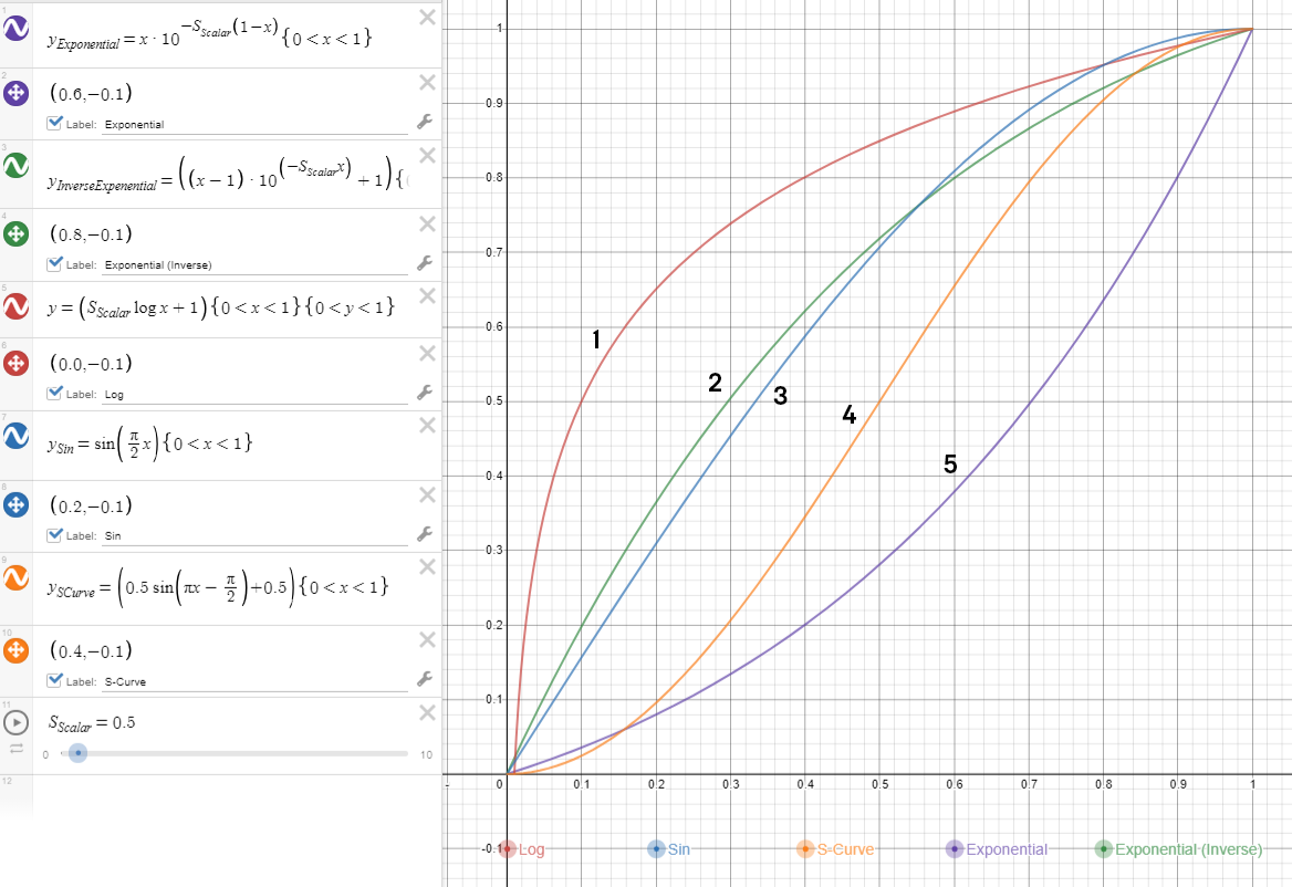
-
(red) Log; 2. (green) Exponential (inverse); 3. (blue) Sin; 4. (orange) S-Curve; 5. (purple) Exponential
Control Bus Mix (USoundControlBusMix)
A Control Bus Mix is a way to drive and group control bus values dynamically at runtime. Multiple mixes can drive a single bus, and multiple buses can be driven simultaneously by a single mix.

With the Control Bus Mix feature, multiple mixes can drive a single bus, and multiple buses can be driven simultaneously by a single mix.
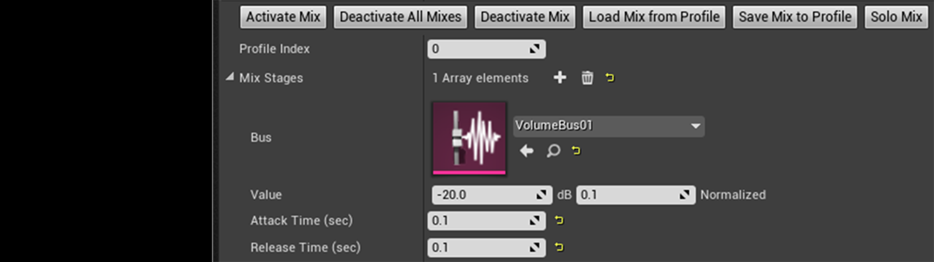
Each control bus mix has an array of Mix Stages . A Mix Stage can be thought of as similar to a channel strip found on a traditional hardware mixer. However, Control Bus Mixes are dynamic—meaning they can have any number of entries, unlike a traditional mixer—and can control virtually any parameter type, not just those canonical values found on a mixer such as volume, pitch, HPF cutoff, LPF cutoff, and trim.
Mix Stages are always associated with a single Modulation Value , and have no direct relation to the traditional definition of a channel in audio (that is, the number of channels in an audio file set, such as mono, stereo, or surround). The name Mix Stage is more related to a traditional gain stage in a volume mix chain, but not limited to volume.
Each Mix Stage provides a Value (displayed in both unit and normalized space), Attack Time , and Release Time . Attack Time is the time it takes for the Mix Stage Value to go from the default value (as defined in the Modulation Parameter for that bus) to the value supplied when the mix is activated. Release Time is the time it takes for the Mix Stage Value to go from its current value back to the default value.
A myriad of functions are exposed as tools in the Details panel when editing Control Bus Mix assets. Activation and deactivation can be auditioned using the functions provided. In addition, a mix can be soloed, or you can deactivate all mixes being auditioned.
Mix profiling
is a way to test out different settings saved as loose config files. For a developer, this can be extremely useful for testing out mixes in a non-shipped build, allowing for fast iteration on perfecting, or testing out new mixes during development. It can even be used to load user-created mixes in a shipped build. Mix profiles are loaded and saved to .ini files at
<ProjectDirectory>Saved\Config\AudioModulation
Load Mix from Profile
and
Save Mix to Profile
functions. Mix profiles are indexed using the
Profile Index
property.
Modulator Activation
All Modulation Sources are activated upon any object being instantiated where they contain a destination that references them. For example, if a Sound Wave with a reference to a Control Bus is played by an Audio Component and that Control Bus is not currently active, it will become active, a process which effectively instantiates a proxy to that Control Bus on the Audio Render Thread. When all references to that Control Bus are destroyed, the Control Bus deactivates, sending a message to the Audio Render Thread to destroy the respective proxy.
Modulation Sources can also be activated by another source referencing them. For example, a Control Bus may become activated if a patch is referenced by a Modulation Destination , and that patch references the given Control Bus.
Optionally, from Blueprint, a client system can hold a handle to a modulator , forcing activation of a bus irrespective of Modulation Destination references being instantiated. This style of explicit management has the benefit of allowing users to feed values to a modulator regardless of whether it is subscribed to. However, utilizing explicit management may require more diligence on the part of the client system to keep tabs on modulator lifetime. An example of when this might be useful includes having a character's ability power be bussed to the audio engine, regardless of whether destinations are actively registered to the modulator.
Blueprint API
(De)ActivateBus/BusMix/Modulator
These calls provide the ability to manually activate and deactivate Control Buses, Bus Mixes, and Modulators (See Modulator Activation ). They respectively no-op (do nothing) if already in the requested state (activated or deactivated).
UpdateModulator
To preserve thread safety, changes to inheriting types of
USoundModulatorBase
(such as
USoundControlBus
,
USoundControlBusMix
, and
USoundBusModulatorLFO
) must be committed via
UpdateModulator
. When provided with a type, all applicable changes to the
USoundModulatorBase
instance will be reflected in the respective runtime instance. For example, if a volume control bus is referenced by a
USoundBase
type and active (with no mixes applied), updating the default value will instantly update the gain stage supplied by that bus to that
USoundBase
instance.
CreateLPFBus/HPFBus/PitchBus/VolumeBus/BusMix/LFO
These are convenience functions for creating respective types, setting a default value, and providing the option to activate immediately.
Save Control Bus Mix to Profile
Saves a control bus mix to a profile, serialized to an .ini file. If the mix is loaded, it uses the state of the current proxy. If not, it uses the default
UObject
representation.
Load Control Bus Mix From Profile
Loads control bus mix from a profile into
UObject
mix definition, deserialized from an .ini file.
Set Control Bus Mix
Sets a mix with the provided stage data if stages provided in active instance proxy of mix. Does not update
UObject
definition of mix.
Set Control Bus Mix By Filter
Sets filtered stages of a given class to a provided target value for active instance of mix. Does not update
UObject
definition of mix unless specified.
Update Control Bus Mix
Commits updates from a
UObject
definition of a bus mix to active proxy in audio render thread. Ignored if mix is inactive.