Choose your operating system:
Windows
macOS
Linux
Projection Policies in nDisplay
As part of the development strategy for new features, Epic Games is constantly evaluating existing tools that could add functionality to Unreal Engine (UE4) . After much research, we found the following technologies to help us achieve our goals for scaled displays.
Here are the currently supported projection policies:
|
Policy |
Description |
|---|---|
|
|
Simple "simple" to be renamed "screen" |
|
|
Camera |
|
|
Manual |
|
|
Mesh-based (added in 4.25) |
|
|
Picp_mesh |
|
|
MPCDI |
|
|
PICP_MPCDI |
|
|
Easyblend |
Simple (To Be Renamed Screen)
Simple refers to the standard policy used to render on regular 2D flat displays. This policy requires a rectangle in 3D space to be used to build camera frustum. The rectangle ( screen ) must be defined in the config file, then referenced in the simple projection policy:
[screen] id="scr_demo" loc="X=2,Y=0,Z=0" rot="P=0,Y=0,R=0" size="X=1,Y=1"
[viewport] id="vp_demo" x="0"  y="0"  width="800" height="800" projection="proj_simple_demo"
[projection] id="proj_simple_demo" type="simple" screen="scr_demo"
In the example above, we define a projection screen that is located 2 meters ahead of the nDisplay root. The screen size is 1x1 meters.
Camera
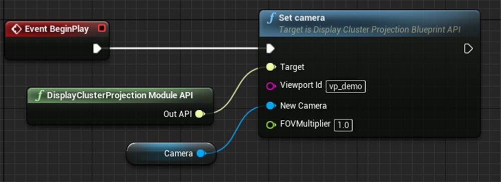
Since it is impossible to get a view from a regular Unreal Engine camera or cine camera with nDisplay, the camera policy was introduced. This policy allows you to map a view of any UE4 camera to the nDisplay viewport.
[viewport] id="vp_demo" x="0"  y="0"  width="800" height="800" projection="proj_camera_demo"
[projection] id="proj_camera_demo" type="camera"

One of the main ideas behind the configuration file is to completely separate the nDisplay topology from the application and its content (Assets). This way, any config file can be used with any application. That is why the camera must be set manually via Blueprints or C++ API.
The same reasoning applies to the mesh policy below.
Manual
As a generic solution for those calibration systems that are not yet supported by nDisplay, a new manual projection policy was introduced. The key idea is that the user explicitly sets a view frustum for a particular viewport.
For stereo rendering, two frustums are required. This can be done either via projection matrix or frustum angles. Here are samples for each approach that include mono and stereo setups:
### Case 1: Frustum from Custom Matrix
[viewport] id=vp_1 x=0   y=0   width=1000  height=600 projection=proj_manual_1
[viewport] id=vp_2 x=0   y=0   width=1000  height=600 projection=proj_manual_2
[projection] id=proj_manual_1 type="manual" rot="P=0,Y=0,R=0" matrix_left="[0.5 0 0 0] [0 0.999999 0 0] [1 0 0 1] [0 0 1 0]" matrix_right="[0.500001 0 0 0] [0 1 0 0] [-1 0 0 1] [0 0 1 0]"
[projection] id=proj_manual_2 type="manual" rot="P=0,Y=0,R=0" matrix="[0.500001 0 0 0] [0 1 0 0] [-1 0 0 1] [0 0 1 0]"
### Case 2: Frustum from Custom Angles
[viewport] id=vp_1 x=0   y=0   width=1000  height=600 projection=proj_manual_1
[viewport] id=vp_2 x=0   y=0   width=1000  height=600 projection=proj_manual_2
[projection] id=proj_manual_1 type="manual" rot="P=0,Y=0,R=0" frustum_left="l=-15 r=0 t=10 b=-10" frustum_right="left=0 right=15 top=10 bottom=-10"
[projection] id=proj_manual_2 type="manual" rot="P=0,Y=0,R=0" frustum="l=0 r=15 t=10 b=-10"
Mesh Based and PICP_Mesh
Two new projection policies were added to simplify warp-rendering workflows:
-
One for general use called
"mesh" -
One for In Camera VFX called
"picp_mesh"( Picture in Camera Perspective , or picp ) -
Instead of a PFM (portable float map) workflow , it is now possible to simply assign a mesh to effectively warp the rendered output.
General Use
*` [projection] id="proj_picpmesh_right" type="mesh" `
-
The source of the warp mesh is represented by SceneMeshComponent reference assigned to the viewport that has "mesh" projection set:
-
[viewport] id="warped_viewport" x="0" y="0" width="1152" height="960" projection="proj_picpmesh_right" -
UV channel 0 used for warp mapping.

In Camera VFX
-
Mesh-based warp "picp_mesh" policy was created for IncameraVFX frustum rendering.
-
[projection] id="proj_picpmesh_up" type="picp_mesh" -
For mesh assignment, the PICP Module API should be used instead of the DisplayClusterProjectionAPI.

MPCDI and PICP_MPCDI
An integration of the MPCDI standard is used for complex projects that rely on this industry protocol.
The MPCDI (Multiple Projection Common Data Interchange) standard was developed by the VESA Multi-Projector Automatic Calibration (MPAC) Task Group. This is a standard data format for projection calibration systems to communicate with devices in a multi-display configuration.
The standard provides a way for multi-projector systems to generate the data needed to combine individual display components into a single, seamless image by a variety of devices. Any new hardware introduced into a system can be easily integrated with the standard.
MPCDI is used throughout the industry by content producers and vendors such as:
-
Scalable Display Technologies
-
VIOSO
-
Dataton Watchout
-
7thSense Design
Support for the MPCDI standard enables nDisplay to read and store data describing a complex projector system in a standardized and formalized fashion, so that we can easily communicate and interface with various other tools from within the industry.
Because the MPCDI implementation is new, there is no previs capability inside the engine yet. To get around this, we are working on a solution for previewing the MPCDI file data within the Unreal Editor, and at runtime.
Currently, users are able to generate procedural meshes of physical displays based on mesh data generated from the MPCDI file.
There are two ways to use mpcdi projection policy. The first is a native approach where the user has to specify the .mpcdi file, buffer, and region to use. The second is where the user explicitly specifies files stored in .mpcdi (which is basically a file archive).
Using the .mpcdi File
[projection] id=proj_mpcdi_demo type="mpcdi" file="D:\config.mpcdi" buffer="Mosaic" region="displayOrigin" origin=mpcdi_origin
Explicit Specification
[projection] id="proj_mpcdi_demo" type="mpcdi" pfm="geom_left.pfm" alpha="geom_left_a.png" beta="geom_left_b.png" scale=1 origin=stage_origin
EasyBlend (Scalable Display)
Integration of EasyBlend calibration data is done with a Scalable SDK that enables warp/blend/keystoning features. This meets the requirement to display on non-planar and complex display surfaces, such as curved or dome-shaped surfaces, using multi-projectors.
Scalable Display Technologies is a company that focuses on software and SDKs for complex projection systems. Their SDK is designed to provide a solution for large displays of a single image through warping and blending. Since Scalable Display Technologies already had the EasyBlend solution in place to handle warping and blending of large images, we chose to integrate it with Unreal Engine.
The Unreal Engine nDisplay supports warp and blend through the integration of the industry-standard middlewares Scalable SDK and EasyBlend for all supported modes, native warp and blend with MPCDI, and custom implementations.
We implemented the integration of EasyBlend to provide a seamless experience in configuring a complex projective system. Once calibration is completed using the third-party tool or software, the user only needs to specify a few parameters in the nDisplay configuration file to get it running.
[projection] id=proj_easyblend_1 type="easyblend" file="E:\LocalCalibrationFlat\ScalableData.pol" origin=easyblend_origin_1 scale=0.1
[projection] id=proj_easyblend_2 type="easyblend" file="E:\LocalCalibrationFlat\ScalableData.pol_1" origin=easyblend_origin_1 scale=0.1
[projection] id=proj_easyblend_3 type="easyblend" file="E:\LocalCalibrationFlat\ScalableData.pol_2" origin=easyblend_origin_1 scale=0.1
VIOSO
Native SDK integration of VIOSO calibration data is available for projector warping and soft edge blending on complex surfaces. Once calibration is completed using VIOSO's tools and software, add a couple parameters to the nDisplay configuration file to use it in your project:
[projection] id=proj_vioso_1 type="vioso" file="D:\left.vwf" origin="origin_vioso" base="[1000 0 0 0] [0 1000 0 0] [0 0 1000 0] [0 0 1000 1]"DomeProjection
Native SDK integration of DomeProjection calibration data is available for projector warping and soft edge blending on massive dome surfaces. Once calibration is completed using DomeProjection's tools and software, add a couple parameters to the nDisplay configuration file to use it in your project:
[projection] id=proj_domeprojection_1 type=domeprojection file="D:\static\config.xml" origin=domeprojection_origin_1 channel=0
[projection] id=proj_domeprojection_1 type=domeprojection file="D:\static\config.xml" origin=domeprojection_origin_1 channel=1
[projection] id=proj_domeprojection_1 type=domeprojection file="D:\static\config.xml" origin=domeprojection_origin_1 channel=2