Choose your operating system:
Windows
macOS
Linux
This sample project is available for download on the Epic Games Launcher in the Learn tab.
The Archviz Interior Rendering sample shows off the realistic rendering possibilities of Unreal Engine 4 (UE4). Explore this small apartment scene that's already been set up to give the best results for a variety of scenarios, so that you can learn the techniques for yourself and even reuse elements in your own work.
This scene utilizes the following techniques for you to learn from:
-
Using physically based materials.
-
Setting up your own master materials and instances.
-
Using and optimizing dynamic lighting techniques with ray tracing.
-
Understanding how to define different sets of ray tracing settings for high quality render output and interactive scene viewing.
Materials
This sample's documentation covers a high-level view of some of the Unreal Engine's Material features. For this reason, it's recommended that you read the Materials documentation to learn more about the concepts and features discussed in this section.
Unreal Engine makes use of a physically based materials system. This makes it possible to approximate what light actually does as opposed to approximating what we think it should do. The end result is more accurate and typically more natural looking. It also means that these types of materials work equally well in all lighting environments while having values that are less complex and interdependent.
It's important that many materials look and react to lighting in a realistic way, especially within this sample project. To better achieve consistency and accuracy, the materials make use of a hierarchical parent-child relationship. This relationship enables us to have a "master" material that has many controllable parameters that adjust different properties or values in the material by passing them effortlessly to a child instance where they can be changed and overridden. This child instance, or
Material Instance
, enables exposed values to be changed and overridden to create any number of variations of its parent material.
Below are some examples of exposed properties that can be adjusted:
|
Property Name |
Sample |
Description |
|---|---|---|
|
Base Color |
Drag the slider to show BaseColor changes.
|
This is the basic color of an object's material. While it's possible to use any texture as a base color, to adhere to physically based lighting, the base color should be devoid of any lighting information. This should simply be the raw color of the underlying material. (See any of our diffuse textures in this project as an example.) |
|
Metallic |
Drag the slider to show Metalness changes.
|
This controls the metalness of the surface for the material. Adjusting it's value to be more metallic controls how much of the surrounding environment overcomes the base color of the object itself. |
|
Roughness |
Drag the slider to show Roughness changes.
|
This controls the diffusion of the specular reflection. It applies the effect of "microfaceting" across the surface. Lower values produce a smoother surface where higher values add more roughness. Consider the difference between the reflection of mirrored chrome compared to brushed aluminum. |


Material Instancing
For a project where a lot of the objects you'll create use similar materials that have similar properties, it can be advantageous to create a master material that exposes these as parameters and values you can set in child instances called a Material Instance .
For the majority of objects in this scene, similar properties are used that have been parameterized for creation of simple variations of the master material or of an existing Material Instance. This means that we can control properties for simple values or swap what types of textures are being used for a material. It also means that individual base Materials aren't required for every object in the scene. This has the advantage of not only being efficient for our project but also efficient for the GPU with regards to performance. This also keeps shader compilation required to a minimum since changing these parameters and properties do not require any additional compilation in most cases.
|
|
|
|
|---|---|---|
|
Master Material (Default Values) |
Material Instance: Base Color Tint Changed |
Material Instance: Diffuse and Normal Texture Swapped |


Master Material Usage
Setting up and using Master Materials is an advanced workflow in Unreal Engine. Before diving into this area of the project, start by looking at the "Material Instance Usage" section of this page, or start learning more about Materials in UE4 with the following documentation:
And visit our Unreal Online Learning portal course Materials - Exploring Essential Concepts .
When setting up your master material, it's important to think ahead about the needs of your project. This means thinking about what properties make sense to expose as a parameter in your Material Instances for your designers and artists. A versatile master material enables you and your teammates to make quick changes to your project with minimal impact without wiping any default values or properties set in the parent material.
The master material assigned to many objects in this scene is called
M_MasterMaterial
.
When setting up a master material for your project, keep the following in mind:
-
What type of objects you'll apply this material to?
-
It's good to separate master material types by their Blend Mode , such as Transparent, Opaque, Masked, and so on.
-
It's also a good idea to use tileable textures for base color, roughness, normals, and so on. Unique texture maps for these objects aren't as versatile and may require additional work.
-
-
What properties and values make sense to expose?
-
If you're using an Opaque or Transparent Blend Mode, what properties and/or values make sense to define the look of specific objects while allowing the flexibility for artists and level designers to make changes effectively.
-
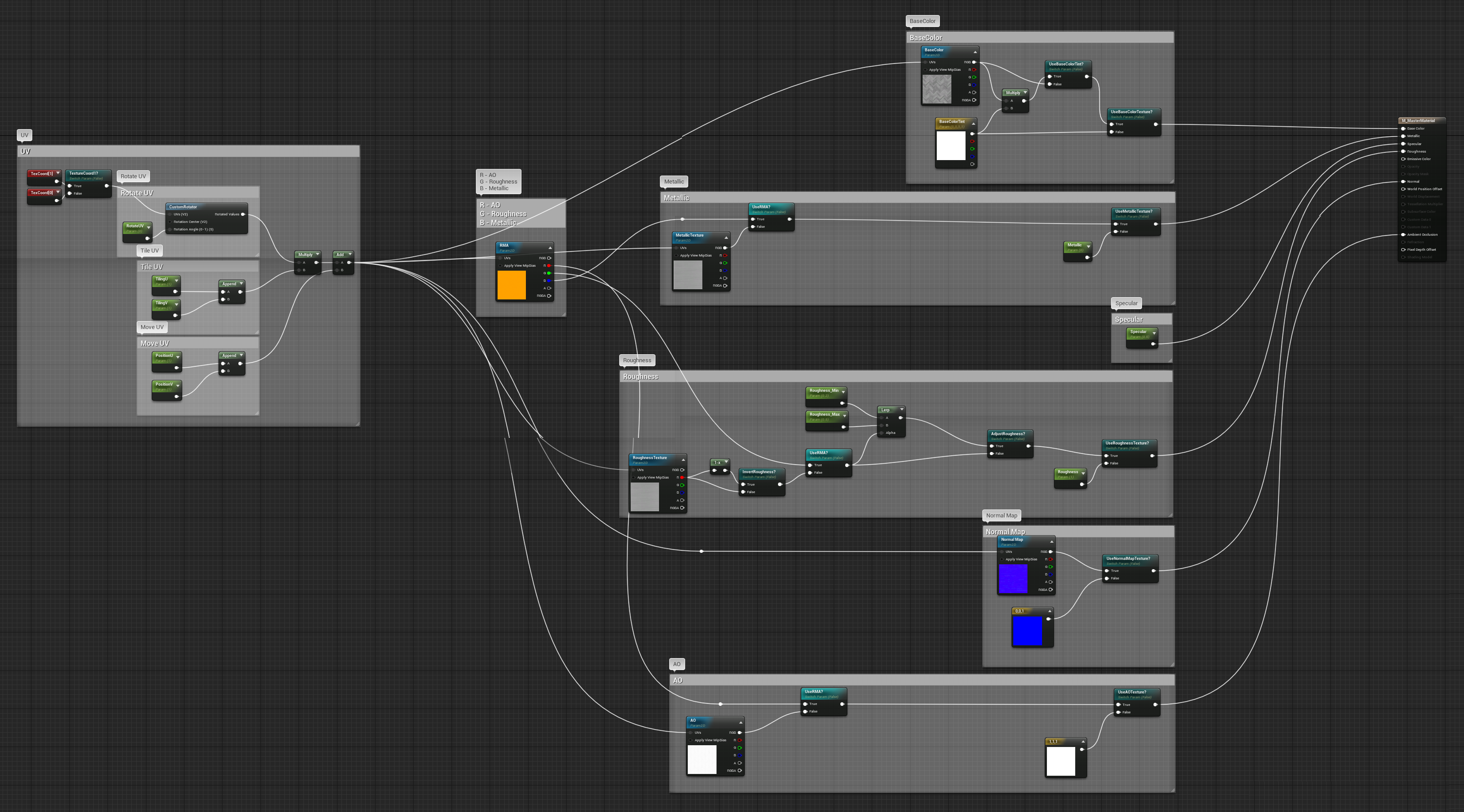
In the master material M_MasterMaterial , let's take a look at how it sets up some general parameters to provide any number of variations using child instances. We'll look at the BaseColor path:

-
A Texture Parameter called BaseColor is used to specify a Texture Asset. When overridden in a Material Instance, the Texture Asset can be exchanged with an compatible texture type, such as Normal or Diffuse ones.
-
A Vector4 Parameter called BaseColorTint is used to change the Texture Asset's color when enabled in a Material Instance. It is useful when wanting to slightly or significantly change the color of an object but not its texture.
-
A couple of Switch Parameters called UseBaseColorTint? and UseBaseColorTexture? are used to enable different paths for setting the base color and/or its tint. Enabling or disabling some of these parameters will expose or remove parameters from being visible in the instance of this material.
This particular master material provides added control to specify textures, color tinting on top of a texture, and more. This amount of flexibility isn't always required. Use your best judgement based on your project's needs, and what makes sense for your artists and level designers.
Material Instance Usage
Once you have your master material set up with the parameters and default values you want to expose, you can create your own instance of a Material Asset which creates a Material Instance Asset.
To do this, right-click any Material Asset in the Content Browser and select Create Material Instance from the context menu.

When you open the instance, you'll find a preview of the material in the Viewport (1). On the right side, you'll find all the exposed properties and values that can be overridden in the Parameter Groups category of the right-hand panel (2).

Under the General category, the Parent assignment box contains the parent material for this Material Instance Asset. The parent material can be either a Material or Material Instance Asset.

Keep in mind that the parent may not always be the master material and may be another instance. A good use case for this may be when you create a fabric or wood material and want to create variations with different colors.
To explore the Materials and Material Instances used in this project, you can locate them in the
Content\Materials
folder.
For additional information on creating your own instances, see the Material Instances page.
Scene Lighting
The look and feel of this interior architectural scene is defined primarily by the way lighting has been setup and how it interacts with the objects and materials used in the scene. For this particular scene, we've made heavy use of our latest Unreal Engine Ray Tracing features for soft area shadowing, accurate reflections from off-screen objects, and real-time global illumination.
Setup Considerations
To achieve the lighting in this scene, some additional lighting setup has been employed to create a photorealistic look using multiple types of lights and settings.
This scene contains the following types of lights and setup:
-
A Directional Light as the primary light source.
-
Multiple Rect Lights to simulate the diffuse contribution from the sky through the windows.
-
Exposure Value of the Post Process Volume that matches physical lighting intensities.
Ray Tracing Features
Lighting
This interior scene mimics the look of being lit using a single light source from the Sun with ambient lighting from the sky using only dynamic lighting and our Ray Tracing features. This setup provides uniform light distribution throughout the scene, reducing areas that could be overly shadowed. Using ray traced shadows, we're able to get sharp contacts with a nice area falloff for soft shadowing in many areas of the apartment.


To make this setup work, we employ the following:
-
A single Directional Light acting as the Sun.
-
The area lights are providing soft illumination to mimic the light entering through the windows, and not necessarily acting as Sunlight.


Reflections
There are many reflective surfaces of varying roughness throughout this interior scene. Some mimic mirror-like surfaces, semi-glossy surfaces, or the scuffed lacquer finish of a floor. Achieving these reflections in the scene adds a quality that simply cannot be achieved without ray tracing them.

Without ray tracing features, reflections are often produced using limited screen space effects which only reflect what is visible on the screen or using static cubemaps that capture an image of the room but aren't dynamic in any way. Ray traced reflections enables you to see the entirety of the scene reflected across surfaces and have multiple bounces to create intr-reflections (or reflections inside of reflections).
Reflections Optimizations
When setting up reflections in this scene, particular care was taken to reduce their costs with minimal quality loss. These are some suggestions and optimizations you can use to achieve similar results in your own projects.
Shiny and Reflective Surfaces
A good first step in optimizing ray-traced reflections is to think about about how smooth or rough materials should be in your scene. Knowing this information lets you decide early on how you want to go about optimizing reflections in the scene. It can provide you with some early "wins" on performance that you don't have to try to earn back later.
If your scene will use a lot of highly reflective surfaces,
There are two paths you should consider:
-
Control roughness/glossiness at the Material-level This workflow gives you finer control through your materials assigned to objects in the scene. Using a good master material can make this easier, but requires manual adjustment within any Materials or Material Instances that needs a specific roughness.
-
Control roughness/glossiness within the Post Process This workflow affects all objects within the scene by limiting roughness to the specified threshold set with the **Max Roughness* property in the Post Process Volume.
Neither of these workflows are exclusive to the other and they can easily be combined. In this sample, there are a lot of reflective surfaces that need to accurately represent the scene. This meant that it made sense to use control roughness at the Material-level for the most flexibility early on in this project. Later, when we were optimizing the scene, it was much easier to strike a balance between performance and quality for what's plausible with the materials used in the scene.
Multiple Reflection Bounces and Noise Reduction
The accuracy of reflections in a scene, especially in an archviz scene like this one, are vitally important to create photorealistic results. However, the costs of using multiple reflection bounces inside of reflections becomes expensive to render in real-time.
First, you can start at the Material-level with a simple optimization using the RayTracingQualitySwitchReplace expression in your master material. This node enables a separate path for ray tracing features in the material to use a less complex material output. Only inputs for BaseColor, Metallic, and Roughness are used in this project. Creating this simpler material path for ray tracing effects means that some costs can be saved with minimal impact to quality.
If we look at this reflection in the television of the floor material
MI_Floor
, it's using a lower resolution texture mip in the Material Instance controlled by the
Mip Bias
in the Material Asset. Without using a mirror-like material or some debug view modes, it'd be hard to notice that this optimization in the Material is taking place for ray traced reflections.

For large surfaces like the floor, walls, and ceiling, you can gain back some frame time with this optimization. Open up the material
M_RTMasterMaterial
to see how the graph using the
RayTracingQualitySwitchReplace
works.
In this comparison, the Viewport's
Reflections
view mode has been enabled to see clear reflections of surfaces in the level. When using all the mip levels (0), this means that the full resolution of the texture is available for streaming in the scene. The floor texture is a 4k texture. When using a mip level of 5, the displayed resolution of the texture is 128. This is more efficient than the full resolution with minimal quality loss in this particular scene.


If you want to see what mip levels are available for your texture, open the Texture Asset and enable the Mip Level checkbox in the toolbar. Then use the plus, minus, or slider to set the preview the mip level.
Another optimization that UE4's ray tracing can use is a fallback option for ray traced reflections to use a Reflection Capture as the last bounce. This has the benefit of reducing costs by using fewer ray-traced reflection bounces and limiting black interreflections on surfaces. Costs of multiple reflection bounces is exponential and cost prohibitive if your project is concerned with runtime performance.
Enable Reflection Capture fallback with the following console command:
r.RayTracing.Reflections.ReflectionCaptures 1


This combination enables fewer artifacts such as the black reflections that happen when only using ray tracing reflections. If you combine using the fallback with two bounces, objects like this where there is a lot of interreflection, you can get much better results.

These optimizations and workflows for reflections also reduce how much noise is generated in reflections when using multiple reflection bounces. Increasing the reflection's Samples Per Pixel setting reduces noise at the cost of performance in the scene, especially in areas with lots of highly reflective surfaces. These are some other ways to reduce noise that appears in reflections:
-
Reduce the complexity of the material and its textures using the RayTracingQualitySwitchReplace node. It reduces noise in the reflection by evaluating the material inputs using with that ray tracing material path instead of the full material path. Textures like normals and smooth surfaces are prone to generating noise in ray traced reflections.
-
Use the Mip Bias property of a Texture Sample to control texture level of detail. Lower quality textures are less likely to generate noise compared to higher quality ones with a lot of texture details.
Global Illumination
Ray traced global illumination (RTGI) enables you to have dynamic bounces of light illuminate the scene from light sources. This project makes use of several illumination methods along with some optimizations to improve performance.
Illumination Methods
Unreal Engine offers two methods of ray traced global illumination for dynamic indirect lighting in the scene:
-
Brute Force uses the slower, more accurate method. This method requires multiple bounces and increased sample counts to reduce artifacts and increase quality at the cost of performance.
-
Final Gather uses the faster, less accurate method. This method uses only a single bounce of indirect lighting with a high number of samples per pixel. It amortizes the cost over multiple frames, giving back runtime performance.
When looking at a still image in this project, there isn't a visibly noticeable difference in quality. However, there is a noticeable performance difference between these two methods.
Both of these methods are used in the sample in some form. While working in the editor and rendering the scene in real time, the Final Gather method is used and is set by default in the Post Process Volume in the level. When we render out high-quality movies using Sequencer , the Brute Force method is used to render the scene. (See the Cinematics section below for additional information.)
Screen Percentage and Samples Per Pixel
One method of increasing performance and illumination in the scene is to adjust the RTGI Screen Percentage (
r.RayTracing.GlobalIllumination.ScreenPercentage
) and Post Process Volume's Ray Traced Global Illumination property for Samples Per Pixel.
The idea behind this is that you can lower the screen percentage of RTGI while increasing the samples count to reduce artifacts and increase uniformity of lighting in the scene with minimal quality loss. However, there is a breaking point where this tradeoff is no longer efficient. For example, having an RTGI screen percentage of 50 with samples per pixel set to 16 is equivalent to an RTGI screen percentage of 100 with sample per pixel 4.


Optimizing Lights with Global Illumination
The following are some suggestions that are used in this project to increase RTGI performance:
-
Each Light Actor has an option to disable its contribution to RTGI. When you have lights that are causing additional GI noise, this can be option to reduce those types of artifacts while also increasing performance by removing this light from GI contribution. Use the property Affect Ray Tracing Global Illumination to toggle the lights GI contribution.
-
Lights that have large occluders in their path are prone to generating more noise in the scene.
-
Disable its GI contribution per-light.
-
Adjust it's radius or move it as to not become as occluded.
-
Remove or adjust large objects in front of these lights that cause more occlusion.
-
-
Using RTGI and ray-traced ambient occlusion (RTAO)
-
Make a decision in your project which has more value for your final render. If you're using RTGI, disable RTAO completely from the Post Process Volume and set the Intensity under the Ambient Occlusion category to 0.
-
-
If there are a lot of objects in the scene that have holes in their geometry, this can be problematic for ray tracing denoisers to solve. Use the RayTracingQualitySwitchReplace expression (see the
Reflectionssection above) to help reduce noise in some cases.
Additional Optimizations, Tips and Tricks
Material Mip Bias with RayTracingQualityReplaceSwitch Expression
Each Texture Sample expression has its own Mip Bias input that can be used. This takes a simple float value, making it possible to control which mip is used for the texture being used. A mip is a given level of detail for a texture; lower mip values result in higher quality and higher values gives lower quality. The Mip Bias property when used in conjunction with the RayTracingQualityReplaceSwitch node lets you specify the maximum quality mip level to use in ray tracing effects.
This can help reduce GPU time spent on mip quality you may not even see. For example, in the material
M_RTMasterMaterial
, the
Mip Bias
for the Albedo is set to -1 as a parameter. Since this material is used only on the floor, ceiling, and walls, those Material Instances use a higher Mip Bias with minimal quality loss. The floor is using a Mip Bias of 5.
This type of trick won't work on every material or surface, but is a good option when optimizing your project trying to get back any bit of performance you can. It's also possible that this reduces the amount of noise visible in some reflections, especially if it's something with a mirror-like surface.
Constant Color Values versus Textures
When creating your master materials, it's a good practice to include a Vector4 expression to accommodate those times when you need a simple color instead of using a texture. Depending on the texture and its size, this can be a resource consumer for your GPU when it's not necessary, especially if the same look can be achieved without the texture. This also has the added benefit of being easier to maintain without bloating your project. That way, if you need to make adjustments to this particular material later on, it's much easier to make these changes as a parameter in a Material Instance than it is to manage a Texture Asset.
Sequencer and Post Process Usage for Cinematic Rendering
This sample provides several ways of viewing content with ray tracing using various settings to balance quality and performance depending on your use case. In all there were three use cases that we identified and demonstrated in this project. Those are:
-
Working in-editor with features and quality representative of the final render while maintaining a real-time frame count.
-
Running the cinematic in Sequencer in real-time in the editor with minimal trade offs in quality for consistent performance.
-
Rendering out the cinematic in Sequencer at non-real time settings.
When working in the editor or running the in-editor cinematic or the non-real time cinematic, there are settings being changed in the background to balance quality and performance for the mode you're entering.
When moving between different modes outlined below, console variables are used to set to control the balance between quality and performance with ray tracing global illumination and ray traced reflections. It is worth noting that when the console variables below are set to a value other than -1, they will override any values set in the Post Process Volume settings. For example, if the command
r.RayTracing.GlobalIllumination
were set to 2, the Post Process Volume setting
Ray Tracing Global Illumination Type
selected method would be ignored until the console variable value is set back to -1.
In-Editor Settings
The in-editor settings represent the ones used when you load the project and ones used while working within the scene. These values are primarily use default ones for the editor or ones that are set within the Post Process Volume in the level. They represent a good balance between quality and performance when using our ray tracing features in real-time.
|
Setting |
Value |
Notes |
|
|---|---|---|---|
|
r.RayTracing.GlobalIllumination |
2 |
This sets the Final Gather GI method. |
|
|
r.RayTracingGlobalIllumination.ScreenPercentage |
unset (default: 50) |
||
|
r.RayTracing.GlobalIllumination.SamplesPerPixel |
16 |
||
|
r.RayTracing.GlobalIllumination.RenderTileSize |
unset (default: 0) |
||
|
r.RayTracing.Reflections.MaxRoughness |
unset (default: 0.6) |
||
|
r.RayTracing.Reflections.SamplesPerPixel |
unset (default: 1) |
||
|
r.RayTracing.Reflections.Shadows |
2 |
This value sets reflections to use Area Shadowing. |
|
In the Post Process Volume, you'll find some of these settings, such as the RTGI Samples Per Pixel, Reflections Max Roughness, and Reflections Shadows type.

Runtime Cinematic Sequencer Settings
Running the runtime cinematic using Sequencer changes the values of the properties outlined below. The values used represent a good balance for this scene and the different shots used during the cinematic.
|
Setting |
Value |
Notes |
|
|---|---|---|---|
|
r.RayTracing.GlobalIllumination |
2 |
This sets the Final Gather GI method. |
|
|
r.RayTracingGlobalIllumination.ScreenPercentage |
100 |
Sets the RTGI screen percentage to 100 percent. |
|
|
r.RayTracing.GlobalIllumination.SamplesPerPixel |
4 |
||
|
r.RayTracing.GlobalIllumination.RenderTileSize |
unset (default: 0) |
||
|
r.RayTracing.Reflections.MaxRoughness |
0.4 |
Sets the max roughness to increase the threshold for reflections reducing the amount of reflections while increasing runtime performance. |
|
|
r.RayTracing.Reflections.SamplesPerPixel |
2 |
Sets the samples per pixel to use fewer samples. This decreases the amount of reflection samples while increasing runtime performance. |
|
|
r.RayTracing.Reflections.Shadows |
unset (default: 1) |
This value sets reflections to use Hard Shadowing. |
|
In these settings, we've made some changes to increase the quality for the in-editor cinematic. A couple of notes on what is changing here and why:
-
The RTGI Screen Percentage has been increased while lowering the RTGI samples per pixel. As shown in a previous section, the in-editor settings of RTGI screen percentage 50 with 16 samples per pixel is equivalent to this change. The exception is that there is some added quality at around the same runtime cost.
-
Reflections max roughness threshold has been changed to reduce the amount of reflections in the scene. This keeps the framerate within budget of 24 frames per second (FPS). Since we're reducing the amount of reflections slightly, it makes sense that we don't need as many samples per pixel for reflections. So, this has been halved from 4 spp to 2 spp for the runtime cinematic, again balancing towards performance when we make these types of changes.
Starting the Runtime Cinematic
-
From the main toolbar, select Cinematics and choose the archviz_cine_MASTER track.
![Seq_Cine_Master.png]()
-
The Sequencer window will open. Next to the Shots track in the left side, click the Camera icon.
![Sequencer_Master.png]()
This locks the viewport to the camera for the runtime cinematic.
-
In the Level Viewport using the main toolbar, click the Play button to play-in-editor.
-
In the Sequencer window, click the Play button to start the cinematic in the Level Viewport.
![Sequencer_Master_Play.png]()


Non-Runtime Cinematic Sequencer Settings
Running the cinematic Sequencer changes values to ones not ideal for real-time. The values here are ideal for rendering a burnout of the cinematic and may take several hours or more to render depending on your graphics card and settings used.
On an Epic developer-spec machine using a NVIDIA Quadro RTX 8000, these settings take approximately eight hours to render this cinematic.
|
Setting |
Value |
Notes |
|---|---|---|
|
r.RayTracing.GlobalIllumination |
1 |
This sets the Brute Force GI method. |
|
r.RayTracingGlobalIllumination.ScreenPercentage |
100 |
Sets the RTGI screen percentage to 100 percent. |
|
r.RayTracing.GlobalIllumination.SamplesPerPixel |
16 |
Uses 16 samples per pixel for RTGI to increase quality at the cost of performance. |
|
r.RayTracing.GlobalIllumination.RenderTileSize |
64 |
Sets the pixel tile size that is submitted to the GPU. For high quality rendering it can prevent driver crashes without triggering timeout detection. |
|
r.RayTracing.Reflections.MaxRoughness |
0.8 |
Sets the max roughness to decrease the threshold for reflections increasing the amount of reflections while decreasing runtime performance. |
|
r.RayTracing.Reflections.SamplesPerPixel |
4 |
Sets the samples per pixel to use more samples. This increases the amount of samples in reflections while decreasing runtime performance. |
|
r.RayTracing.Reflections.Shadows |
unset (default: 1) |
This value sets reflections to use Area Shadowing. |
Running the Sequencer in-editor may cause the UE4 editor to lock up. These settings are intended to be used to render out a video using Sequencer Render Movie Settings . (See the next section below.)
Rendering the Cinematic Sequence as a Movie
-
From the main toolbar in the Level Viewport, select the Cinematics dropdown and choose the archviz_cine_MASTER_MaxQuality track.
![Seq_Cine_MaxQuality.png]()
-
The Sequencer cinematic window will open. In the toolbar, select the Clap Board icon to open the Render Movie Settings window.
![Sequencer_MaxQuality.png]()
This window includes all the settings for rendering out this Sequencer cinematic.
![RenderMovieSettings.png]()
-
Chose the Image Output Format you'd like to use from the dropdown selection.
![CapMovieImageOutput.png]()
For our videos, we've used Image Sequence (bmp) and professional video software to compile those into a final video we render out.
-
There are many other options here for you to choose from for rendering out your video. For example, select a Resolution you want to render at, the directory where these images are saved, and so on.
-
When you're ready, click the Capture Movie button at the bottom. It will open a preview window
![CaptureMoviePreview.png]()


For added quality at the cost of time, you can use the console command
r.ScreenPercentage
to set the screen percentage to a higher value, such as 150, when rendering out the video/image cinematic. The cinematic at the top of this page was rendered using this approach. The resolution of the image sequence was set to 1920x1080 and then super sampled with the screen percentage change.
Controlling the Values in Sequencer
-
-
From the main toolbar in the Level Viewport, select the Cinematics dropdown and choose a Sequence from the Edit Existing Cinematic list.
![ControllingSeq1.png]()
-
-
The selected Sequencer cinematic window will open. In the toolbar, select the Wrench dropdown menu and select Open Director Blueprint .
![Seq_OpenDirector.png]()


In this SequenceDirector Blueprint, you'll find the following:

-
There are tabs that are used to set and reset RTGI settings for this Sequence.
-
The Variables category contains array variables with the console variables and their values outlined in the previous sections for "Runtime Cinematic Sequencer Settings" and "Non-Runtime Cinematic Sequencer Settings."
-
When an array variable is selected, its array elements and values are shown under the Default Value category. For example, when looking at the Sequencer cinematic "archviz_cine_MASTER" with the RTGI_CVars_On variable selected, the values there match those listed in the table under the "Runtime Cinematic Sequencer Settings" section of this page.
Acknowledgements
We'd like to thank Pasquale Scionti of www.sciontidesign.com for leading the design work on this scene and creating its mood and ambiance. Pasquale has been an avid user of Unreal Engine and its ray tracing implementation since the earliest releases, helping push its development along the way. You can see more of his work with Unreal Engine on a special section of his website .