Choose your operating system:
Windows
macOS
Linux
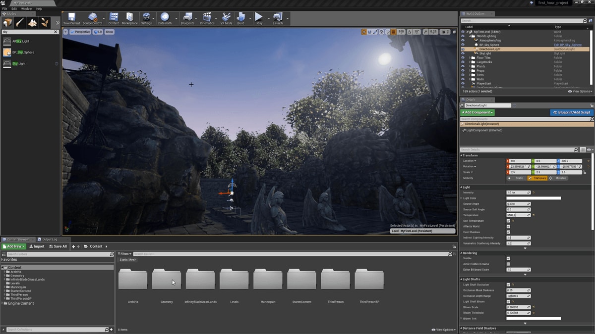


The Unreal Editor viewports have a large number of visualization modes to help you see the type of data being processed in your scene, as well as to diagnose any errors or unexpected results. The more common view modes have their own hotkeys, but all can be accessed from the viewport within the View Mode menu.


Lit

-
View Mode Hotkey: Alt + 4
-
Console command:
viewmode lit
Lit view mode shows the final result of your scene once all of the Materials and lighting have been applied.
Unlit

-
View Mode Hotkey: Alt + 3
-
Console command:
viewmode unlit
Unlit view mode removes all lighting from the scene, showing you Base Color only.
Wireframe

-
View Mode Hotkey: Alt + 2
-
Console command:
viewmode wireframe
Wireframe shows all of the polygon edges in the scene. In the case of Brushes, you will see the resultant geometry.
Detail Lighting

-
View Mode Hotkey: Alt + 5
-
Console command:
viewmode lit_detaillighting
Detail Lighting activates a neutral Material across the entire scene, using the normal maps of the original materials. This is useful for isolating whether your BaseColor is obscuring lighting by being too dark or noisy.
Lighting Only

-
View Mode Hotkey: Alt + 6
-
Console command:
viewmode lightingonly
Lighting Only shows a neutral Material that is only affected by lighting. It differs from Detail Lighting mode in that you will not see normal maps.
Light Complexity

-
View Mode Hotkey: Alt + 7
-
Console command:
viewmode lightcomplexity
Light Complexity shows the number of non-static lights affecting your geometry. This is useful for tracking lighting cost - the more lights affecting a surface, the more expensive it will be to shade.
|
Light Complexity Coloration |
||||||
|---|---|---|---|---|---|---|
|
Color |
|
|
|
|
|
|
|
Number of Lights Affecting Surface |
0 |
1 |
2 |
3 |
4 |
5+ |


This color scheme is defined in the shader code.
Shader Complexity

-
View Mode Hotkey: Alt + 8
-
Console command:
viewmode shadercomplexity
Shader Complexity Mode is used to visualize the number of shader instructions being used to calculate each pixel of your scene. It is generally a good indication of how performance-friendly your scene will be. In general, it is used to test overall performance for your base scene, as well as to optimize particle effects, which tend to cause performance spikes with a large amount of overdraw for a short period of time.
Only instruction count is used to calculate shader complexity, which may not always be accurate. For example, a shader with 16 instructions, all texture lookups, will be much slower on all platforms than a shader with 16 math instructions. Also shaders which contain loops that are not unrolled will not be represented accurately by the instruction count, this is mainly an issue for vertex shaders. Overall the instruction count is a good metric in the vast majority of cases.
The view mode uses a color spectrum to indicate how expensive the scene is. Green through red represent a linear relationship of "very inexpensive" to "expensive", while pink and white indicate a large jump to "very expensive" pixels. Small areas of white can be tolerated, but if the majority of your screen is covered in bright red or white, the performance will be poor.
|
Shader Complexity Coloration |
|||||||||
|---|---|---|---|---|---|---|---|---|---|
|
|
|
|
|
|
|
|
|
|
|
|
Ideal |
Moderate |
Expensive |
Very Expensive |
||||||
+ShaderComplexityColors
is defined in the
BaseEngine.ini
file and is linearly interpolated (lerped) based on the total number of instructions for a given pixel.
+ShaderComplexityColors=(R=0.0,G=1.0,B=0.127,A=1.0)
+ShaderComplexityColors=(R=0.0,G=1.0,B=0.0,A=1.0)
+ShaderComplexityColors=(R=0.046,G=0.52,B=0.0,A=1.0)
+ShaderComplexityColors=(R=0.215,G=0.215,B=0.0,A=1.0)
+ShaderComplexityColors=(R=0.52,G=0.046,B=0.0,A=1.0)
+ShaderComplexityColors=(R=0.7,G=0.0,B=0.0,A=1.0)
+ShaderComplexityColors=(R=1.0,G=0.0,B=0.0,A=1.0)
+ShaderComplexityColors=(R=1.0,G=0.0,B=0.5,A=1.0)
+ShaderComplexityColors=(R=1.0,G=0.9,B=0.9,A=1.0)
MaxPixelShaderAdditiveComplexityCount
is set to a default range of 2000, however, this value can be changed in the
BaseEngine.ini
file to help with the optimization of materials in your project.
MaxPixelShaderAdditiveComplexityCount=2000MaxES3PixelShaderAdditiveComplexityCount defines the range in the ES3 Preview Mode and is set to a default range of 800.
`MaxES3PixelShaderAdditiveComplexityCount=800`
These Colors can be modified in the
BaseEngine.ini
file. The max pixel shader additive complexity count variables can also be overridden in your project's
DefaultEngine.ini
file.
Stationary Light Overlap

-
View Mode Hotkey: None (Menu only by default)
Lightmap Density

View Mode Hotkey: Alt + 0
Lightmap Density mode displays the lightmap density of objects that are texture mapped, color coding them by their relation to an ideal/max density setting and displaying a grid that maps to the actual lightmap texels. It is important to have even texel density across your scene to get consistent lightmap lighting.
|
|
|
|
|---|---|---|
|
Less than ideal texel density |
Ideal texel density |
Max or greater than ideal texel density |


Skeletal Meshes will appear in light brown and are not considered in this calculation.
Reflections

-
View Mode Hotkey: None (Menu only by default)
Reflections view mode overrides all materials with a flat normal and a roughness of 0, which is a mirror. This is useful for diagnosing the detail of reflections and allowing you to place more Reflection Capture Actors in areas where you need more detail.
LOD Coloration

-
Console command:
viewmode LODColoration
LOD Coloration view mode displays the current LOD index of a primitive. This is useful for diagnosing any LOD issues or to see at which distance your LODs are switching.
|
LOD Primitive Coloration |
||||||||
|---|---|---|---|---|---|---|---|---|
|
Color |
|
|
|
|
|
|
|
|
|
LOD Primitive Color |
0 |
1 |
2 |
3 |
4 |
5 |
6 |
7 |


+LODColorationColors=(R=1.0,G=1.0,B=1.0,A=1.0)
+LODColorationColors=(R=1.0,G=0.0,B=0.0,A=1.0)
+LODColorationColors=(R=0.0,G=1.0,B=0.0,A=1.0)
+LODColorationColors=(R=0.0,G=0.0,B=1.0,A=1.0)
+LODColorationColors=(R=1.0,G=1.0,B=0.0,A=1.0)
+LODColorationColors=(R=1.0,G=0.0,B=1.0,A=1.0)
+LODColorationColors=(R=0.0,G=1.0,B=1.0,A=1.0)
+LODColorationColors=(R=0.5,G=0.0,B=0.5,A=1.0)
By default the engine uses only four LODs, but this can be extended in the source code.
HLOD Coloration

-
Console command:
viewmode hlodcoloration
HLOD Coloration view mode displays the Hierarchial LOD Cluster index of a primitive.
|
HLOD Primitive Coloration |
|||||
|---|---|---|---|---|---|
|
Color |
|
|
|
|
|
|
HLOD Primitive Color |
0 |
1 |
2 |
3 |
4 |

+HLODColorationColors=(R=1.0,G=1.0,B=1.0,A=1.0) //white (not part of HLOD)
+HLODColorationColors=(R=0.0,G=1.0,B=0.0,A=1.0) //green (part of HLOD but being drawn outside of it)
+HLODColorationColors=(R=0.0,G=0.0,B=1.0,A=1.0) //blue (HLOD level 0)
+HLODColorationColors=(R=1.0,G=1.0,B=0.0,A=1.0) //yellow (HLOD level 1)
+HLODColorationColors=(R=1.0,G=0.0,B=1.0,A=1.0) //purple
+HLODColorationColors=(R=0.0,G=1.0,B=1.0,A=1.0) //cyan
+HLODColorationColors=(R=0.5,G=0.5,B=0.5,A=1.0) //grey
Buffer Visualization

The Buffer Visualization area offers you access to individual buffers within the graphics card, which can help you diagnose problems how your scenes look. In order to make the most out of the buffer visualization modes, it will help to understand the basics of Material Inputs and Material Properties .
Buffer Overview

The Buffer Overview visualization mode allows you to see multiple images from the graphics card's GBuffer. Many of these correlate to inputs on Materials, meaning you can see how the scene looks with just a single Material input being used.
Base Color

-
View Mode Hotkey: None (Menu only by default)
The Base Color mode allows you to see the only the Base Color of the Materials in your scene.
Decal Mask

-
View Mode Hotkey: None (Menu only by default)
The Decal Mask mode shows in white any surface which can receive deferred decals. Objects which cannot appear in black.
Diffuse Color

-
View Mode Hotkey: None (Menu only by default)
Diffuse Color shows the result of Base Color and the Material's Ambient Occlusion inputs.
Shading Model

-
View Mode Hotkey: None (Menu only by default)
The Shading Model mode shows value of the Shading Model property for each Material in the scene.
|
Light Complexity Coloration |
||||
|---|---|---|---|---|
|
Color |
|
|
|
|
|
Material's Shading Model |
Default Lit |
Unlit |
Subsurface |
Preintegrated Skin |


Material AO


-
View Mode Hotkey: None (Menu only by default)
The Material AO visualization mode shows the result of any texturing or Material Expression nodes that are connected to the Material's Ambient Occlusion input.
Metallic

-
View Mode Hotkey: None (Menu only by default)
The Metallic visualization mode shows the result of any texturing or Material Expression nodes that are connected to the Material's Metallic input.
Note: Materials should generally have Metallic values of 0 or 1, not in between. Values between 0 and 1 will happen due to layer blending, but physical materials will always be a metal or not.
Opacity


-
View Mode Hotkey: None (Menu only by default)
Opacity visualization mode shows the result of any texturing or Material Expression nodes that are connected to the Material's Opacity input. In the images above, you can see the dreadlocks on the character are somewhat transparent.
The Opacity viewmode only shows opaque materials with Opacity being used, which is important in the case of subsurface scattering materials, as the Opacity controls how far light can penetrate.
Roughness

-
View Mode Hotkey: None (Menu only by default)
Roughness visualization mode shows the result of any texturing or Material Expression nodes that are connected to the Material's Roughness input. Roughness variation is where a lot of reflection variation will come from.
Scene Color

-
View Mode Hotkey: None (Menu only by default)
Scene Color shows the result of the scene before any post processing is done. This means before any exposure, bloom, color correction, or antialiasing. In the above image, the scene appears very dark because exposure has not brightened it up for us.
Scene Depth

-
View Mode Hotkey: None (Menu only by default)
Scene Depth shows the depth of the scene in a constant gradient from white (farthest away) to black (closest).
Separate Translucency RGB

-
View Mode Hotkey: None (Menu only by default)
Separate Translucency RGB shows the color information of any Materials that are Translucent and using Separate Translucency.
Separate Translucency A

-
View Mode Hotkey: None (Menu only by default)
Separate Translucency A shows only the alpha information of any Materials that are Translucent and using Separate Translucency.
Specular Color

-
View Mode Hotkey: None (Menu only by default)
Specular Color shows the color being imparted to the specular reflections of a Material. Generally, this is inferred from a combination of the Base Color and Metallic values.
Specular

-
View Mode Hotkey: None (Menu only by default)
Specular shows the results of any texturing or Material Expression nodes that are fed into a Material's Specular input.
Subsurface Color

-
View Mode Hotkey: None (Menu only by default)
Subsurface Color shows the results of any texturing or Material Expression nodes that are fed into a Material's Subsurface Color input.
World Normal

-
View Mode Hotkey: None (Menu only by default)
World Normal shows the world space normal of any opaque surfaces.
Ambient Occlusion

-
View Mode Hotkey: None (Menu only by default)
Ambient Occlusion (AO) shows the result of any ambient occlusion calculations that are taking place on the scene. This is separate from any AO textures applied to Materials, as this is a calculation the engine makes based on surfaces and normal maps.
Landscape Visualizers
Normal

The Normal Landscape visualization mode shows a Landscape in its normal, lit state.
LOD

The LOD Landscape visualization mode breaks a landscape up into color-coded panels which represent their current LOD state.
Layer Density

The Layer Density Landscape visualization mode shows the landscape in a color-coded mode which shifts from green to red as more layers are added to the Landscape.
Exposure
Exposure is a post-processing effect that controls the overall brightness of a scene. This can be set to a fixed value or left to automatic.
Automatic vs. Fixed Exposure
When playing games with Exposure activated in your post processing, you will notice that moving from a light to a dark area or vice versa will cause the camera to temporarily adjust, similarly to how our eyes adjust when moving to different light environments. In most cases, this will be the desired result. However, if the constant shifting is distracting in your particular level, then you can set the view to a fixed exposure. This will lock the exposure in place so it no longer automatically changes as you move from light to dark or dark to light, but it also means that you can easily end up in a situation where the lights are overbright or overdark for the work you need to do.