Choose your operating system:
Windows
macOS
Linux


Utility Expressions nodes are nodes that can affect Materials in a number of different ways than one might be used to. For example the GIReplace node will Replace an objects indirect bounce color with a given value you input while the Linear Interpolate node will help blend between two Textures based on an Alpha input. On the following page you will find detailed descriptions for all of the Utility Expressions nodes that are available in the UE4 Material Editor.
AntialiasedTextureMask
The AntialiasedTextureMask expression allows you to create a material using a soft (anti-aliased) transition mask. The mask can be used to blend between two complex material properties or to fade out an alpha blended material (works well with SoftMasked). Simply specify a texture with the mask specified in one channel (red, green, blue, or alpha), set the used channel in the expression and specify the comparison value. Assuming the channel stores a grayscale value in the range 0 = black to 1 = white the comparison function defines if the resulting mask should be 0 or 1. This expression is a parameter, allowing the Texture property to be overridden by child MaterialInstances.
|
Item |
Description |
|
|---|---|---|
|
Properties |
||
|
Threshold |
Specifies the value used as the cutoff point in pixel coverage. Pixel coverage values less than this become black; values greater become white. |
|
|
Channel |
Specifies the channel of the Texture to use as the mask. |
|
|
Texture |
Specifies the mask texture to use. |
|
|
Inputs |
||
|
UVs |
Takes in texture coordinates to apply to the texture mask. |
|
Pseudo code:
Result = 1
if TextureLookup < Threshold then Result = 0
The actual implementation is quite a bit more complicated as it tries to return values between 0 and 1 depending on the actual pixel coverage to avoid aliasing.
Example (this tiny 128x128 texture, uncompressed for best quality):

Was used as a normal texture (left top) and used with the described material expression (bottom right):

The technique works best in magnification and with blurred input content. Compression hurts the quality a lot so try to use uncompressed low resolution textures.
BlackBody
The BlackBody expression simulates the effects of black body radiation within your Material. The user inputs a temperature (in Kelvin) and the resulting color and intensity can be used to drive Base Color and Emissive values to get a physically accurate result.

BumpOffset
BumpOffset is the Unreal Engine 4 term for what is commonly known as 'Parallax Mapping'. The Bump Offset expression allows a material to give the illusion of depth without the need for additional geometry. BumpOffset materials use a grayscale heightmap to give depth information. The brighter the value in the heightmap, the more 'popped out' the material will be; these areas will parallax (shift) as a camera moves across the surface. Darker areas in the heightmap are 'further away' and will shift the least.
|
Item |
Description |
|
|---|---|---|
|
Properties |
||
|
HeightRatio |
Multiplier for the depth taken from the heightmap . The larger the value, the more extreme the depth will be. Typical values range from 0.02 to 0.1. |
|
|
ReferencePlane |
Specifies the approximate height in texture space to apply the effect. A value of 0 will appear to distort the texture completely off the surface, whereas a value of 0.5 (the default) means that some of the surface will pop off while some areas will be sunken in. |
|
|
Inputs |
||
|
Coordinate |
Takes in base texture coordinates to be modified by the expression. |
|
|
Height |
Takes in the texture (or a value) to be used as the heightmap. |
|
|
HeightRatioInput |
Multiplier for the depth taken from the heightmap . The larger the value, the more extreme the depth will be. Typical values range from 0.02 to 0.1. If used, this input supersedes any value in the Height Ratio property. |
|

ConstantBiasScale
The ConstantBiasScale expression takes an input value, adds a bias value to it, and then multiplies it by a scaling factor outputting the result. So for example, to convert input data from [-1,1] to [0,1] you would use a bias of 1.0 and a scale of 0.5.
|
Item |
Description |
|
|---|---|---|
|
Properties |
||
|
Bias |
Specifies the value to be added to the input. |
|
|
Scale |
Specifies the multiplier for the biased result. |
|

DDX
The DDX expression exposes DDX derivative calculation, a GPU hardware feature used in pixel shader calculation.
DDY
The DDY expression exposes DDX derivative calculation, a GPU hardware feature used in pixel shader calculation.
DepthFade
The DepthFade expression is used to hide unsightly seams that take place when translucent objects intersect with opaque ones.
|
Item |
Description |
|
|---|---|---|
|
Properties |
||
|
Fade Distance |
World space distance over which the fade should take place. This is used if the FadeDistance input is unconnected. |
|
|
Inputs |
||
|
Opacity |
Takes in the existing opacity for the object prior to the depth fade. |
|
|
FadeDistance |
World space distance over which the fade should take place. |
|


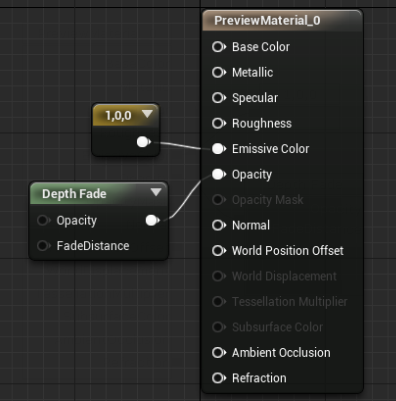
Click image for full size view.
DepthOfFieldFunction
The Depth of Field Function expression is designed to give artists control over what happens to a Material when it is being blurred by Depth of Field. It outputs a value between 0-1 such that 0 represents "in focus" and 1 represents "completely blurred." This is useful for interpolating between sharp and blurry versions of a texture, for instance. The Depth input allows for the existing results from the scene's Depth of Field calculations to be overridden by other calculations.


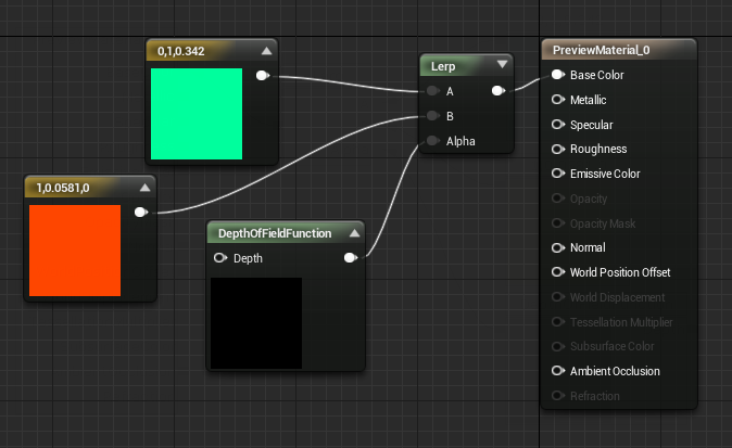
Click image for full size view.
Desaturation
The Desaturation expression desaturates its input, or converts the colors of its input into shades of gray, based a certain percentage.
|
Item |
Description |
|
|---|---|---|
|
Properties |
||
|
Luminance Factors |
Specifies the amount that each channel contributes to the desaturated color. This is what controls that green is brighter than red which is brighter than blue when desaturated. |
|
|
Inputs |
||
|
Fraction |
Specifies the amount of desaturation to apply to the input. Percent can range from 0.0 (full original color, no desaturation) to 1.0 (fully desaturated). |
|

Programmers:
Define desaturated color
D
, input color
I
and luminance factor
L
. The output will be
O = (1 - Percent)*( D.dot( I )) + Percent * I
Distance
The Distance expression computes the (Euclidian) distance between two points/colors/positions/vectors and outputs the resulting value. This works on one, two, three and four component vectors, but both inputs to the expression must have the same number of channels.
|
Item |
Description |
|
|---|---|---|
|
Inputs |
||
|
A |
Takes in a value or vector of any length. |
|
|
B |
Takes in a value or vector of any length. |
|

Pseudo code:
Result = length (A - B)Low level HLSL code:
float Result = sqrt (dot (A-B, A-B))DistanceFieldGradient
The DistanceFieldGradient Material Expression node, when normalized, outputs the X,Y,Z direction an object would move with in the distance field. This makes the Distance Field Gradient Material Expression node well-suited for Materials that need to simulate the flow of liquids.
Generate Mesh Distance Fields must be enabled in Project Settings under Rendering for this expression to work correctly.
|
Item |
Description |
|---|---|
|
Position |
Defaults to current World Position if nothing is input. |
Here is an example of how to use the DistanceFieldGradient Material Expression in your Materials. In this example below make sure to note that the DistanceFieldGradient was first normalized and then input into a Mask Channel node. The reason for this is because without normalizing the DistanceFieldGradient first you can not get directional data. The Mask Channel Parameter was added to allow for easier RGB channel switching with in the Material Instance.

Click image for full size view.
Here is an example of the DistanceFieldGradient in action. The image below shows what data the DistanceFieldGradient will use when the various RGB are enabled.
Click image for full size view.
|
Number |
Description |
|---|---|
|
1 |
Enabling the R channel and disabling all other channels. |
|
2 |
Enabling the G channel and disabling all other channels. |
|
3 |
Enabling the B channel and disabling all other channels. |
DistanceToNearestSurface
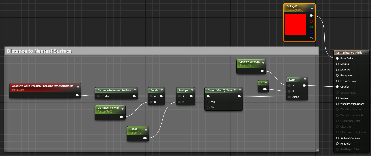
The Distance To Nearest Surface Material Expression node allows Materials to sample any point in the levels Global Distance Field. This Material Expression works by outputting the signed distance in world space units from the distance field to the nearest occluders in the scene.
Generate Mesh Distance Fields must be enabled in Project Settings under Rendering for this expression to work correctly.
|
Item |
Description |
|---|---|
|
Position |
Defaults to current World Position if nothing is input. |
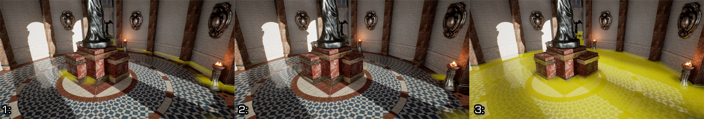
Here is an example of the Distance To Nearest Surface Material Expression in action.
Click image for full size view.

In this example the Distance To Nearest Surface was fed into the Opacity input on a Material and that Material was applied to a Static Mesh plane that was placed just above the levels floor. What the Distance To Nearest Surface is doing is telling the Material to only color areas red were the Static Meshes plane will start to intersect other Static Meshes placed in the scene.
FeatureLevelSwitch
The Feature Level Switch node allows you to make simplified materials for lower powered devices.
Example Usage : You might have a material with 10 textures overlapping and complex math, but just a single static texture for mobile (feature level ES2).
|
Item |
Description |
|
|---|---|---|
|
Inputs |
||
|
Default |
The default Feature Level. |
|
|
ES2 |
Feature Level defined by the core capabilities of OpenGL ES2. |
|
|
ES3.1 |
Feature Level defined by the capabilities of Metal-level devices. |
|
|
SM4 |
Feature Level defined by the core capabilities of DX10 Shader Model 4. |
|
|
SM5 |
Feature Level defined by the core capabilities of DX11 Shader Model 5. |
|
Fresnel
The Fresnel expression calculates a falloff based on the dot product of the surface normal and the direction to the camera. When the surface normal points directly at the camera, a value of 0 is output. When the surface normal is perpendicular to the camera, a value of 1 is output. The result is clamped to [0,1] so you do not have any negative color in the center.
|
Item |
Description |
|
|---|---|---|
|
Properties |
||
|
Exponent |
Specifies the how quickly the output value falls off. Larger values mean tighter or quicker falloff. |
|
|
Base Reflect Fraction |
Specifies the fraction of specular reflection the surface is viewed from straight on. A value of 1 effectively disables the Fresnel effect. |
|
|
Inputs |
||
|
ExponentIn |
Specifies the how quickly the output value falls off. Larger values mean tighter or quicker falloff. If used, value will always supersede the Exponent property value. |
|
|
Base Reflect Fraction |
Specifies the fraction of specular reflection the surface is viewed from straight on. A value of 1 effectively disables the Fresnel effect. If used, value will always supersede the Exponent property value. |
|
|
Normal |
Takes in a three-channel vector value representing the normal of the surface, in world space. To see the results of a normal map applied to the surface of the Fresnel object, connect the normal map to the Normal input of the material, then connect a PixelNormalWS expression to this input on the Fresnel. If no normal is specified, the tangent normal of the mesh is used. |
|

GIReplace
GIReplace
allows artists to specify a different, usually simpler, expression chain when the material is being used for GI.
Example Usage : Lightmass static GI and LPV dynamic GI use it.
|
Item |
Description |
|
|---|---|---|
|
Inputs |
||
|
Default |
The default GI. |
|
|
StaticIndirect |
Used for baked indirect lighting. |
|
|
DynamicIndirect |
Used for dynamic indirect lighting. |
|
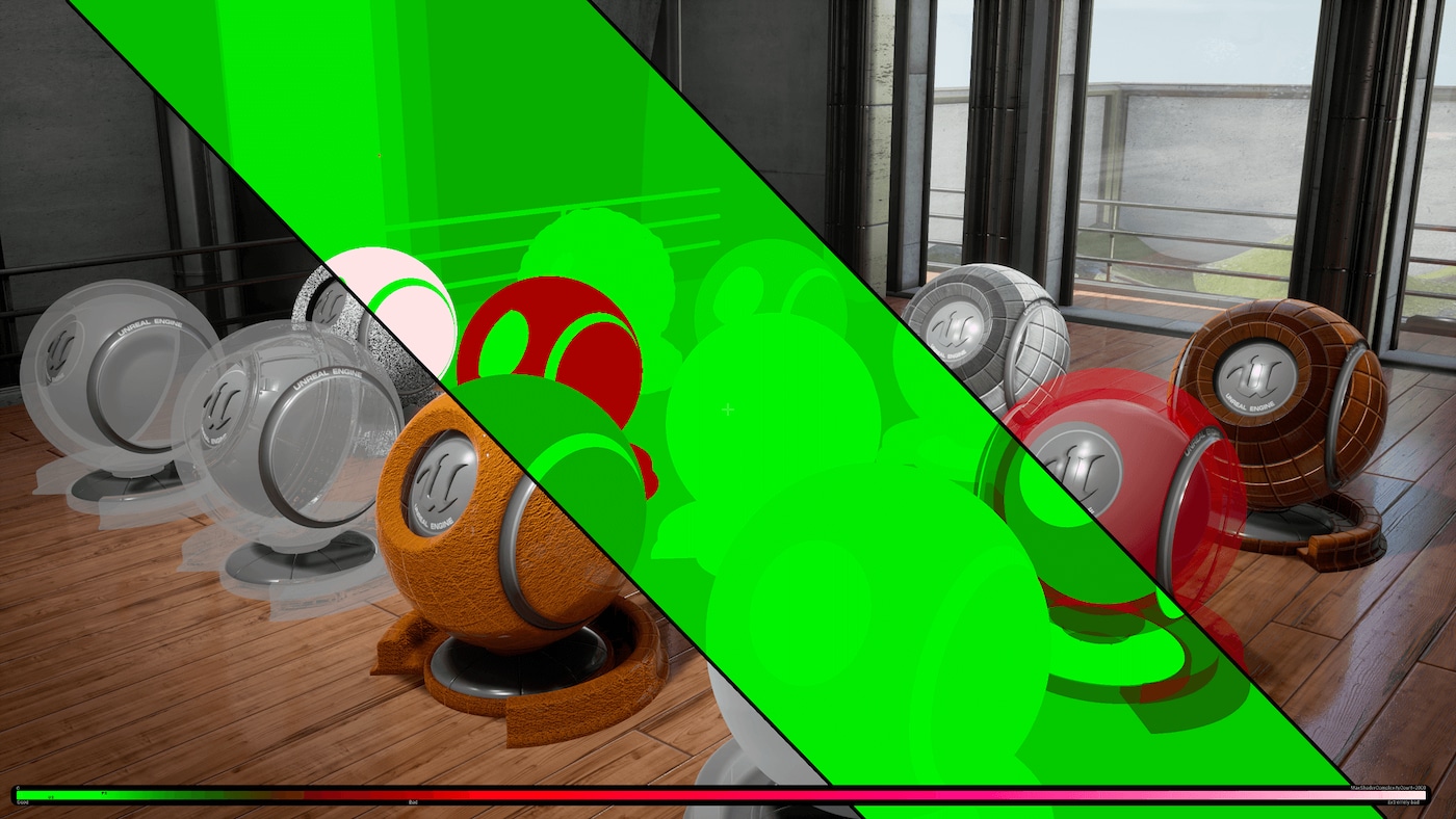
Notice the two red boxes - one is bouncing off green instead of red.
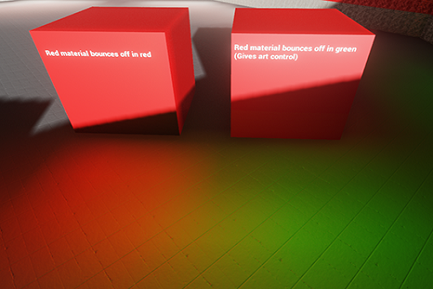
This was achieved by using a new material expression.

Normally you do not want to have a completely different color but some darkening, brightening, or a minor color adjustment can be useful.
LightmassReplace
The LightmassReplace expression simply passes through the Realtime input when compiling the material for normal rendering purposes, and passes through the Lightmass input when exporting the material to Lightmass for global illumination. This is useful to work around material expressions that the exported version cannot handle correctly, for example WorldPosition.
|
Item |
Description |
|
|---|---|---|
|
Inputs |
||
|
Realtime |
Takes in the value(s) to pass through for normal rendering. |
|
|
Lightmass |
Takes in the value(s) to pass through when exporting the material to Lightmass. |
|
LinearInterpolate
The LinearInterpolate expression blends between two input value(s) based on a third input value used as a mask. This can be thought of as a mask to define transitions between two textures, like a layer mask in Photoshop. The intensity of the mask Alpha determines the ratio of color to take from the two input values. If Alpha is 0.0, the first input is used. If Alpha is 1.0, the second input is used. If Alpha is between 0.0 and 1.0, the output is a blend between the two inputs. Keep in mind that the blend happens per channel. So, if Alpha is an RGB color, Alpha's red channel value defines the blend between A and B's red channels independently of Alpha's green channel, which defines the blend between A and B's green channels.
|
Item |
Description |
|
|---|---|---|
|
Properties |
||
|
Const A |
The value mapped to 0.0. Only used if the A input is unconnected. |
|
|
Const B |
The value mapped to 1.0. Only used if the B input is unconnected. |
|
|
Const Alpha |
Takes in the value to use as the mask alpha. Only used if the Alpha input is unconnected. |
|
|
Inputs |
||
|
A |
Takes in the value(s) mapped to 0.0. |
|
|
B |
Takes in the value(s) mapped to 1.0. |
|
|
Alpha |
Takes in the value to use as the mask alpha. |
|
Programmers: LinearInterpolate does a per-channel lerp between A and B based on the parametric value Alpha.

Noise
The Noise expression creates a procedural noise field, giving you control over how it is generated.
|
Item |
Description |
|||||||||||||||||||||
|---|---|---|---|---|---|---|---|---|---|---|---|---|---|---|---|---|---|---|---|---|---|---|
|
Properties |
||||||||||||||||||||||
|
Scale |
Changes the overall size of the noise cells. Lower numbers make the noise bigger. |
|||||||||||||||||||||
|
Quality |
A look/performance setting. Lower values are faster but may look worse, higher values are slower but may look better. |
|||||||||||||||||||||
|
Function |
|
|||||||||||||||||||||
|
Turbulence |
With Turbulence on, each noise octave will add only absolute values to the result. Changes the visual characteristics and can great shapes resembling sharp mountain ridges |
|||||||||||||||||||||
|
Levels |
How many different levels of noise at different scales to combine, multiplies the computational cost by the number of levels. |
|||||||||||||||||||||
|
Output Min |
The lowest value output by the noise calculation. |
|||||||||||||||||||||
|
Output Max |
The highest value output by the noise calculation. |
|||||||||||||||||||||
|
Level Scale |
Level scale is always active and determines how much the scale changes for each new octave. |
|||||||||||||||||||||
|
Tiling |
For noise functions that support it, allows noise to tile. This is more expensive, but useful when baking noise into a seamless wrapping texture. |
|||||||||||||||||||||
|
Repeat Size |
When tiling, how often should the noise repeat. |
|||||||||||||||||||||
|
Inputs |
||||||||||||||||||||||
|
Position |
Allows the texture size to be adjusted via a 3D vector. |
|||||||||||||||||||||
|
FilterWidth |
In effect, controls how much blur will be applied to the noise texture. |
|||||||||||||||||||||

Previous Frame Switch
The Previous Frame Switch Material Expression enables you to support complex vertex animations implemented in your materials to generate correct motion vectors so that they can work correctly with Temporal AA and Motion Blur.
Materials that are only a function of time already work without modification, however, they cannot account for other variables, such as Material Parameters, that can affect the animation. The Previous Frame Switch Material Expression enables Artists to solve these types of problem manually by tracking how these parameters change, for instance, in Blueprints, where they can manually provide expressions for motion vector generation that is caused by changes in World Position Offset between frames.
Velocities from vertex deformation must be enabled in Project Settings under Rendering for this expression to work:
-
4.24 and later versions use Accurate velocities from Vertex Deformation
-
4.25 and future versions use Output velocities from vertex deformation
|
Item |
Description |
|---|---|
|
Current Frame |
Directional Vector used as the starting position reference. |
|
Previous Frame |
Directional Vector used as the XYZ reference for the amount of blur to add. |
Here is an example using Previous Frame Switch Material Expression in a Material.

In this example, the Previous Frame Switch is using a constant value to control the directional blur through a Multiply node.
In this example, you can see how this is being used in Epic's own games, like Fortnite, to control the motion blur with a Vertex Animation that assembles on screen. The animation on the right is using Previous Frame Switch to add some motion blur, while the animation on the left is not.
QualitySwitch
The QualitySwitch expression allows for the use of different expression networks based on the engine is switched between quality levels, such as using lower quality on lower-end devices.
|
Item |
Description |
|
|---|---|---|
|
Inputs |
||
|
Default |
This input is used for networks designed for default visual quality. |
|
|
Low |
This input is used for networks designed for lower visual quality. |
|
|
High |
This input is used for networks designed for higher visual quality. |
|
RotateAboutAxis
The RotateAboutAxis expression rotates a three-channel vector input given the rotation axis, a point on the axis, and the angle to rotate. It is useful for animations using WorldPositionOffset that have better quality than simple shears.
|
Item |
Description |
|
|---|---|---|
|
Inputs |
||
|
NormalizedRotationAxis |
Takes in a normalized (0-1) vector which represents the axis about which the object will rotate. |
|
|
RotationAngle |
The angle of rotation. A value of 1 equals a full 360-degree rotation. |
|
|
PivotPoint |
Takes in the three-channel vector representing the pivot point about which the object will rotate. |
|
|
Position |
Takes in the three-channel vector representing the position of the object. When the RotateAboutAxis expression is created, a WorldPosition expression is automatically created and connected to this input. |
|

In the above example, the preview plane would appear to spin on its vertical axis.
SphereMask
The SphereMask expression outputs a mask value based on a distance calculation. If one input is the position of a point and the other input is the center of a sphere with some radius, the mask value is 0 outside and 1 inside with some transition area. This works on one, two, three, and four component vectors
|
Item |
Description |
|
|---|---|---|
|
Properties |
||
|
Attenuation Radius |
Specifies the radius to use for the distance calculation. |
|
|
Hardness Percent |
Specifies the transition area size. This works like the Photoshop brush hardness value. 0 means the transition is hard, 100 means the transition area is maximal(soft). |
|
|
Inputs |
||
|
A |
Takes in the value representing the position of the point to check. |
|
|
B |
Takes in the value representing the center of the sphere. |
|

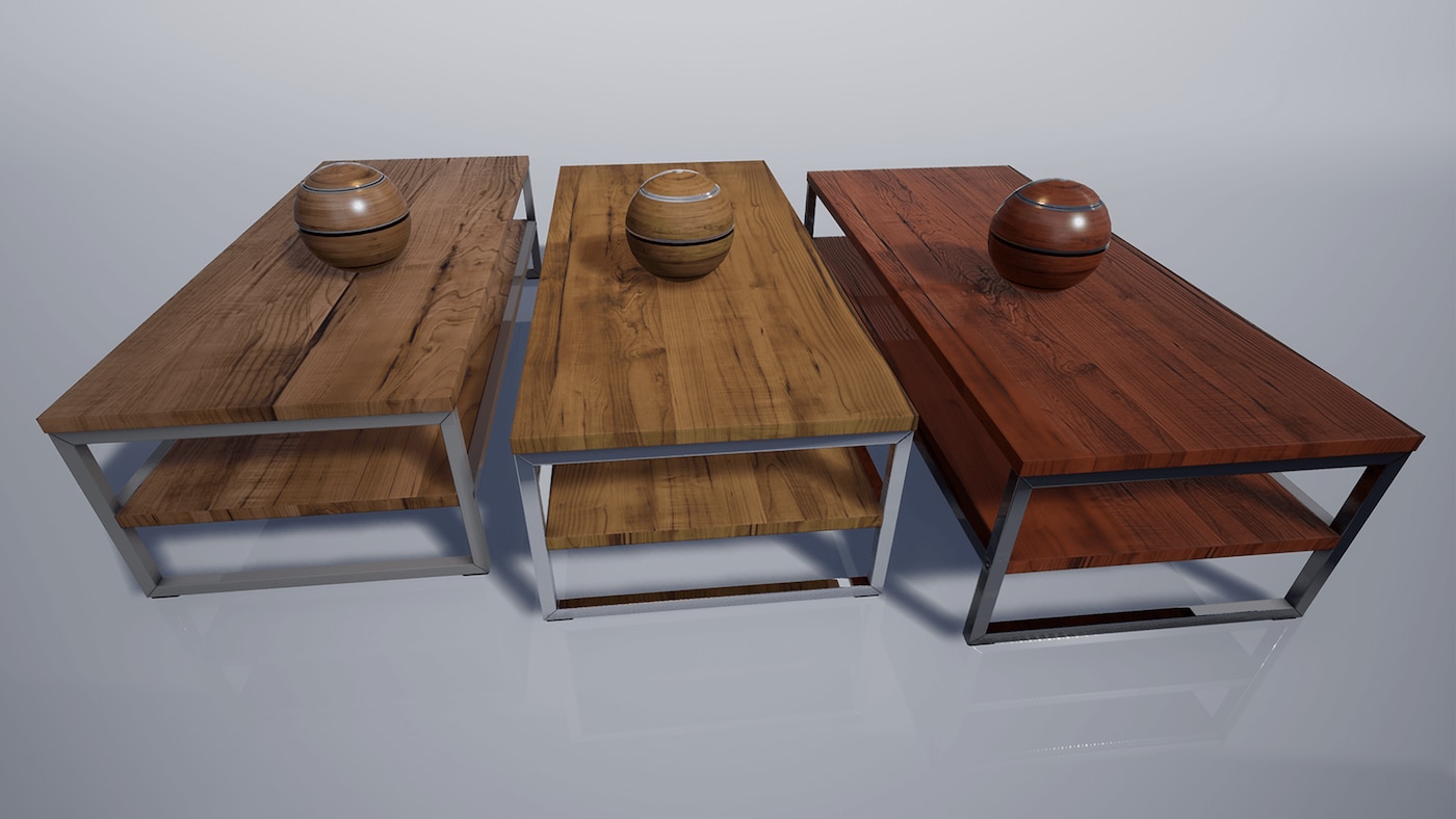
In this example, the preview object will smoothly fade to black as the camera exceeds 256 units away from it.
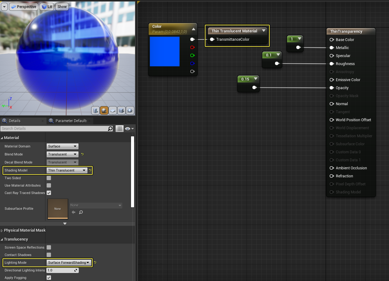
Thin Translucent
The Thin Translucent Material Output expression accurately represents physically based transparent materials in a single pass. This enables you to create true tinted or colored transparent materials that accurately respond to lighting and shading.
Click image for full size.
When creating a tinted glass material, a white specular highlight and tinted background are needed. These are rendered in a single pass with a physically based shader that accounts for light bounces from the air into the glass and the glass into the air.


Enable Thin Translucent material output by setting the following in the Material Details panel:
-
Blend Mode: Translucent
-
Shading Model: Thin Translucent
-
Lighting Mode: Surface ForwardShading
Vector Noise

The Vector Noise Material expression adds several more 3D or 4D vector noise results to use in your Materials. Due to the run-time expense of these functions, it is recommended that once a look is developed with them, all or part of the computation be baked into a Texture using the Draw Material to Render Target Blueprint feature introduced in Unreal Engine 4.13 and later. These Material graph Expressions allow procedural looks to be developed in the engine on final assets, providing an alternative to creating procedurally generated Textures with an external tool to apply to assets in UE4. Inside of the Vector Noise Material Expression, you will find the following Vector Noise types.
|
Image |
Item |
Description |
|---|---|---|
|
|
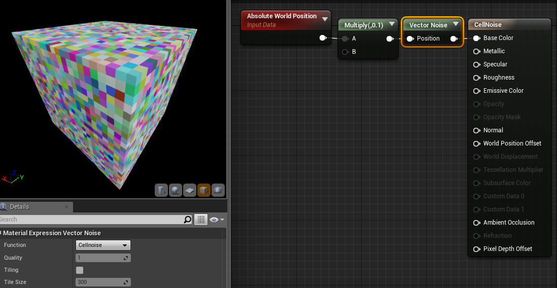
Cellnoise |
Returns a random color for each cell in a 3D grid (i.e. from the mathematical floor operation applied to the node input). The results are always consistent for a given position, so can provide a reliable way to add randomness to a Material. This Vector Noise function is extremely cheap to compute, so it is not necessary to bake it into a Texture for performance. |
|
|
Perlin 3D Noise |
Returns a random color for each cell in a 3D grid (i.e. from the mathematical floor operation applied to the node input). The results are always consistent for a given position, so can provide a reliable way to add randomness to a Material. This Vector Noise function is extremely cheap to compute, so it is not necessary to bake it into a Texture for performance. |
|
|
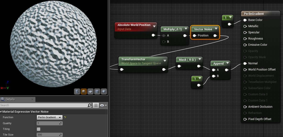
Perlin Gradient |
Computes the analytical 3D gradient of a scalar Perlin Simplex Noise. The output is four channels, where the first three (RGB) are the gradient, and the fourth (A) is the scalar noise. This noise type is useful for bumps on a surface or for flow maps. |
|
|
Perlin Gradient |
Computes the analytical 3D curl of a vector Perlin Simplex Noise (aka Curl Noise). The output is a 3D signed curl vector and is useful for fluid or particle flow. |
|
|
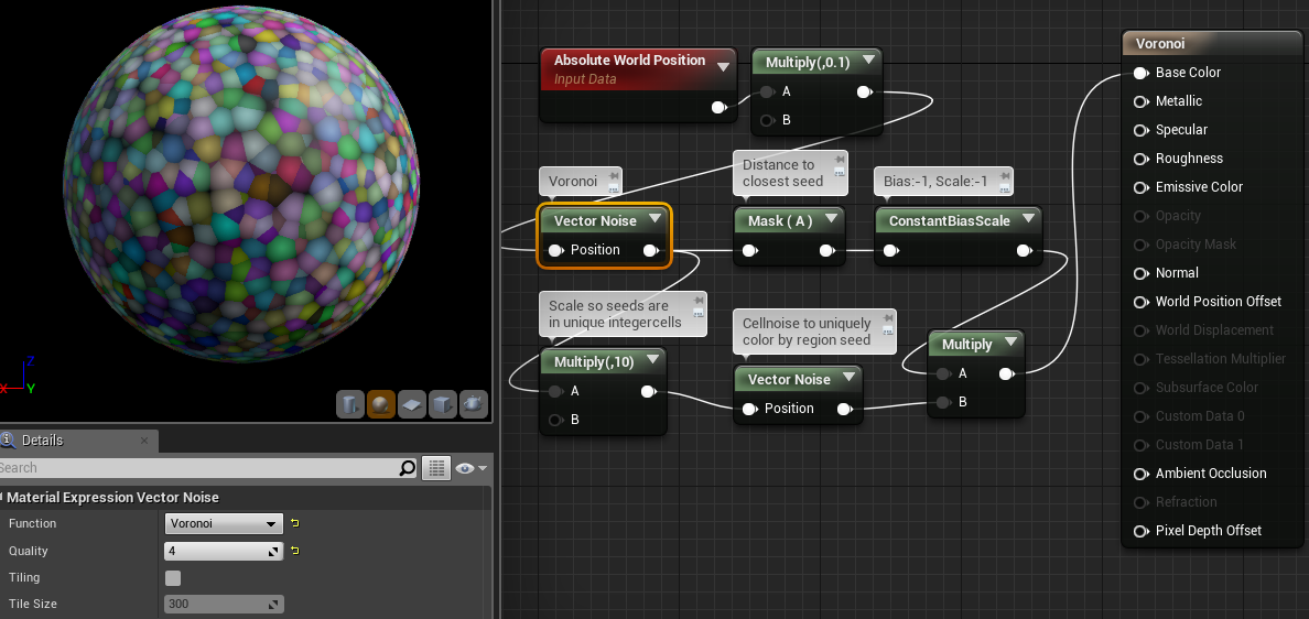
Voronoi |
Computes the same Voronoi noise as the scalar Noise material node. The scalar Voronoi noise scatters seed points in 3D space and returns the distance to the closest one. The Vector Noise version returns the location of the closest seed point in RGB, and the distance to it in A. Especially coupled with Cellnoise, this can allow some randomized behavior per Voronoi cell. |


Below is a simple stone bed material using the distance component of the Vector Noise / Voronoi to modulate some surface bumps and blend in moss in the cracks, and the seed position together with Vector Noise / Cellnoise to change the color and bump height per rock.

The derivative-based operations Perlin Curl and Perlin Gradient can be added together in octaves, just as regular Perlin noise can. For derivatives of more complex expressions, it is necessary to compute the gradient of the result of the expression. To help with this, place the expression to compute into a Material Function and use it with the following helper nodes.
|
Item |
Description |
|---|---|
|
Prepare3DDeriv |
Uses positions offset in a tetrahedral pattern to compute 3D derivatives. Evaluate the same 3D function at each offset position produced by this function, then feed the resulting values into Compute3DDeriv. |
|
Compute3DDeriv |
Uses positions offset in a tetrahedral pattern to compute 3D derivatives. Use with Prepare3DDeriv. |
|
GradFrom3DDeriv |
Computes 3D gradient vector from result of Prepare3DDeriv/Compute3DDeriv. |
|
CurlFrom3DDeriv |
Computes curl of a 3D vector field from result of Prepare3DDeriv/Compute3DDeriv. |
These helper Material Functions use four evaluations of the base expression spaced in a tetrahedral pattern to approximate these derivative-based operations.
Below you will find descriptions of the various noise functions you will find in the Vector Noise Material Expression.
|
Item |
Description |
||||||||||||
|---|---|---|---|---|---|---|---|---|---|---|---|---|---|
|
Properties |
|||||||||||||
|
Function |
|
||||||||||||
|
Quality |
A look/performance setting. Lower values are faster but may look worse, higher values are slower but may look better. |
||||||||||||
|
Tiling |
For noise functions that support it this allows noise to tile. This is more expensive, but useful when baking noise into a seamless wrapping texture. |
||||||||||||
|
Tile Size |
When tiling, how often should the noise repeat. For Perlin noise variants, the Tile Size must be a multiple of three. |
||||||||||||
|
Inputs |
|||||||||||||
|
Position |
Allows the texture size to be adjusted via a 3D vector. |
||||||||||||
-
Cell Noise Material Example:
![Cellnoise.png]()
Click for full image.
-
Perlin Gradient Material Example:
![PerlinGradient.png]()
Click for full image.
-
Voronoi Material Example:
![Voronoi.png]()
Click for full image.