Choose your operating system:
Windows
macOS
Linux
In order to understand and use the content on this page, make sure you are familiar with the following topics:
For some effects, you may need to spawn tens of thousands of particles. However, using the standard CPU to generate this many particles can cause performance issues. In this guide, we will show you how to create a sprite particle effect that uses the GPU instead of the CPU to run the simulation.
Create the System and Emitter
Niagara emitters and systems are independent. The current recommended workflow is to create a system from existing emitters or emitter templates.
-
First, create a Niagara System by right-clicking in the Content Browser, and from the displayed menu select FX > Niagara System . The Niagara System wizard displays.

Click image for full size.
-
Select New system from selected emitters . Then click Next .

Click image for full size.
-
Under Templates , select Simple Sprite Burst .

Click image for full size.
-
Click the Plus icon ( + ) to add the emitter to the list of emitters to add to the system. Then click Finish .

Click image for full size.
-
Name the new system GPUSprite . Double-click to open it in the Niagara Editor.

Click image for full size.
-
The emitter instance in your new system has the default name of SimpleSpriteBurst , but you can rename it. Click the name of the emitter instance in the System Overview , and the field will become editable. Name the emitter FX_GPUSprite .

Click image for full size.
1.Drag the GPUSprite system into your Level.
When you make a particle effect, it is always a good idea to drag your system into your Level. This gives you a chance to see every change and edit in context. Any changes you make to the system automatically propagate to the instance of the system in your Level.


Emitter Settings - Emitter Properties
First, you need to change some settings in the Emitter Properties . This is where you switch from CPU simulation to GPU simulation.
-
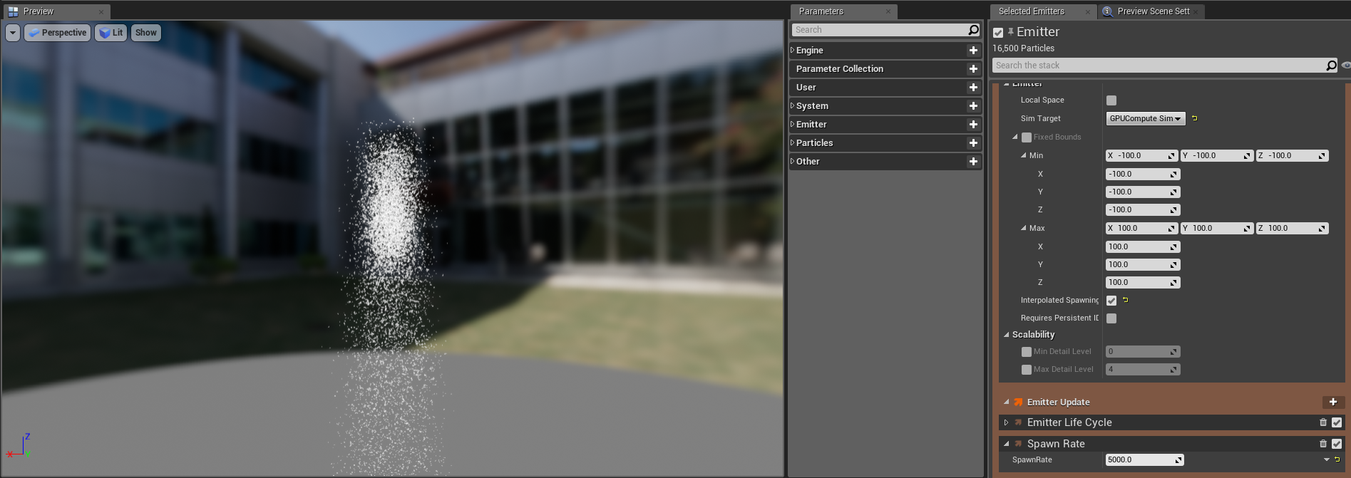
In the System Overview , click Emitter Settings to open it in the Selection panel.

Click image for full size.
-
Expand Emitter Properties . Locate the Sim Target field. This is where you tell Unreal Engine to use the GPU for the simulation. Click the dropdown and select GPUComputeSim .

Click image for full size.
-
You may trigger a warning about the Fixed Bounds not being set. Click the box for Fixed Bounds . This will resolve the error. Leave the Minimum and Maximum set to the default values.
Because the particle simulation is done on the GPU, the system cannot read how big the effect is. This is why it is necessary to set fixed bounds. You can do so in the emitter, as shown in this step, or you can set fixed bounds for the entire system in the System Properties item.


Emitter Update Group Settings
Next, you will edit the modules in the Emitter Update group. These are behaviors that apply to the emitter, and that update each frame.
-
In the System Overview , click Emitter Update to open it in the Selection panel.

Click image for full size.
-
Expand the Emitter State module. This module controls time and scalability for this emitter. Because you used the Simple Sprite Burst template, the Life Cycle Mode is set to Self . Normally this is used for complete customization of emitter life cycle logic for this specific emitter, but it is not needed for this effect. Click the dropdown and set the Life Cycle Mode to System . This enables your system to calculate the life cycle settings, which usually optimizes performance. By default, the system loops infinitely on a 5 second interval.

Click image for full size.
-
The Spawn Burst Instantaneous module creates a large burst of particles when the emitter spawns. This module is included in the Simple Sprite Burst template. Set the Spawn Count to 2500 . Because Spawn Time is set to 0 , the burst occurs immediately upon startup.

Click image for full size.
-
For this effect, you need more than just a burst of particles when the emitter spawns. The Spawn Rate module creates a continuous stream of particles while the emitter is active. Add the Spawn Rate module by clicking the Plus sign icon ( + ) for Emitter Update and selecting Spawning > Spawn Rate .

Click image for full size.
-
Set the Spawn Rate to 500 . This will spawn particles at the rate of 500 per second, which will provide a continuous stream of particles after the initial burst.

Click image for full size.


Particle Spawn Group Settings
Next, you will edit the modules in the Particle Spawn group. These are behaviors that apply to particles when they first spawn.
-
In the System Overview , click Particle Spawn to open it in the Selection panel.

Click image for full size.
-
Expand the Initialize Particle module. This module collects several related parameters together in one module, minimizing clutter in your stack. Under Point Attributes , locate the Lifetime parameter.
-
The Lifetime parameter determines how long particles will display before they disappear. For this effect you want a constant value, so that the particles will display for the entire duration of the effect. Set the Lifetime to 5 .

Click image for full size.
-
You will make the sprite size randomized in another part of this guide, but here we will set the base size of the sprite. Under Sprite Attributes , locate the Sprite Size parameter and make sure it is enabled. Set the Sprite Size to the following.

Click image for full size.
Size Vector
Value
X
5
Y
5
-
Sphere location controls the shape of the location where sprites spawn. By adding the Sphere Location module, the sprites spawn in a sphere shape, and you can set the size of the sphere shape by indicating a radius. Add the Sphere Location module by clicking the Plus sign icon ( + ) for Particle Spawn and selecting Location > Sphere Location . You can leave the default settings for this module.

Click image for full size.


Particle Update Group Settings
Now you will edit the modules in the Particle Update group. These behaviors apply to an emitter's particles and update each frame.
-
In the System Overview , click the Particle Update group to open it in the Selection panel.

Click image for full size.
-
In the Initialize Particle module of the Particle Spawn group, you picked the base size of the sprites. You can randomize the size of the sprites by adding the Scale Sprite Size module. This applies a scaling factor to the base size. Add the Scale Sprite Size module by clicking the Plus sign icon ( + ) and selecting Size > Scale Sprite Size .

Click image for full size.
-
The default values for Scale Sprite Size are X: 1 and Y: 1 . Changing these default values will uniformly make all the particles bigger or smaller. However, random size variation is more visually interesting than a static size. Click the downward arrow next to the Scale Factor field, and select Dynamic Inputs > Vector2D from Float .

Click image for full size.
-
Notice that the value for Scale Factor has changed to one static value. There are several ways to add a float value, depending on what you want the particles to look like. For a flowing and gradual size change, a curve is ideal. Click the downward arrow next to Value , and select Dynamic Inputs > Float from Curve .

Click image for full size.
-
The curve you added in step 5 has two default values. You can add more keys to the curve to make the size variation more complex. Right-click on the line, and select Add Key to Curve . Do this again, so that you have a total of 4 keys displaying on the curve.

Click image for full size.
-
Set the four keys on the curve to the following values.

Click image for full size.
Key Number
Time
Value
1
0
0
2
.25
1
3
.75
1
4
1
0
-
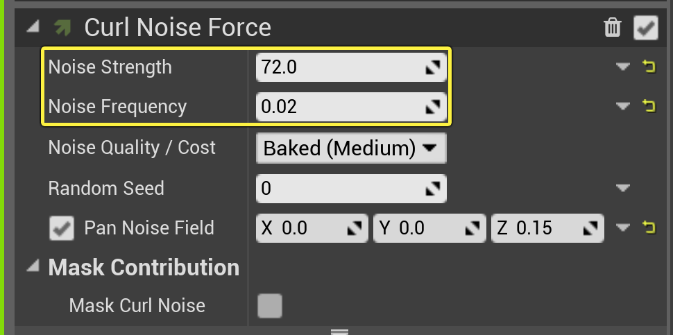
Right now, your current settings just create a ball of particles that is not very interesting. You can add some additional elements that increase the variation and movement of the particles. Click the Plus sign icon ( + ) for Particle Update, and select Forces > Curl Noise Force .

Click image for full size.
-
There are a lot of things you can do with Curl Noise Force. Noise Strength controls how large the overall noise field is (in other words, how much the noise disrupts the original sphere of particles). Noise Frequency controls how often the curl noise is applied to the particles: the smaller the number, the more warped the sphere location of the particles will become. Use the settings below for now, but later you can experiment with these to get a different look.
![Curl Noise Settings]()
Click image for full size.
Parameter
Value
Noise Strength
72
Noise Frequency
.02
-
Now you will see that the particles swirl at first, then just move outward continuously until they die. For this effect, the particles should move outward and then back in toward their origin point, to make a swirling mass. The Point Attraction Force module makes the particles move toward a single point (by default, this point is the emitter's position). Click the Plus sign icon ( + ) for Particle Update, and select Forces > Point Attraction Force .

Click image for full size.
-
Attraction Strength is the amount of force pulling the particles to the attractor point. Attraction Radius delineates the size of the field in which the point attraction force applies to the particles. The Falloff Exponent controls how much the sphere spreads; the smaller the number, the more the sphere of particles spreads out. The Kill Radius sets the size of the area where the particles dissolve at the end of their life cycle. Set the Attraction Strength , Attraction Radius , Falloff Exponent , and Kill Radius to the following values.
Click the triangle at the bottom of the module to display the Kill Radius parameter. Check the box to enable it, if it is not already checked.

Click image for full size.
Parameter
Value
Attraction Strength
5.5
Attraction Radius
300.0
Falloff Exponent
0.6
Kill Radius
4.0
-
Now for changing the color. Click the Plus sign icon ( + ) for Particle Update and select Colors > Color .

Click image for full size.
-
You can add a color stop to the curve by clicking the space above the colored bar, and you can change the color by double clicking a stop to open the Color Picker. To set an opacity stop, click in the space below the bar. Set the colors and opacity as shown below.

Click image for full size.
Color or Opacity Stop
Time
Values
Color
Stop 1
0.0
R: 1, G: 0, B: 1
Stop 2
.35
R: .08, G: 0, B: 1
Stop 3
..60
R: .2 , G: 1, B: .8
Stop 4
.8
R: 1, G: .96, B: .3
Opacity
Stop 1
0
1
Stop 2
.7
1
Stop 3
1
0


End Result
Congratulations! You've created a cool sprite effect that uses the GPU instead of the CPU.