Choose your operating system:
Windows
macOS
Linux
This page describes how Datasmith imports scenes from most supported CAD file formats into Unreal Editor. It follows the basic process outlined in the Datasmith Overview and About the Datasmith Import Process , but adds some special translation behavior that is specific to CAD files. If you're planning to use Datasmith to import scenes from CAD files into Unreal Editor, reading this page can help you understand how your scene is translated, and how you can work with the results in Unreal Editor.
CAD Workflow
Datasmith uses a Direct workflow for most CAD file types. This means that to get your content into Unreal using Datasmith, you need to:
-
Save your CAD scene to one of the supported file types .
-
Enable the Importers > Datasmith CAD Importer Plugin for your Project, if it's not already installed.
-
Use the Datasmith importer available in the Toolbar of the Unreal Editor to import your file. See Importing Datasmith Content into Unreal Engine 4 .
To read more about other types of Datasmith workflows, see Datasmith Supported Software and File Types .
Tessellation
In CAD formats, you often use curves and mathematical functions to define surfaces and solids. The precision and smoothness of these surfaces is ideal for the manufacturing process. However, modern GPU chips are highly optimized for rendering surfaces that are made up of triangular meshes. Real-time renderers and game engines like Unreal, which need to push the limits of these GPUs in order to produce dozens of stunning photoreal quality images every second, typically only work with geometry that is made up of triangular meshes.
Datasmith bridges this gap by automatically computing triangular meshes that closely approximate any curved surfaces in your CAD file that don't already have mesh representations. This process is called tessellation , and it is an essential step in preparing your CAD data for use in real time.
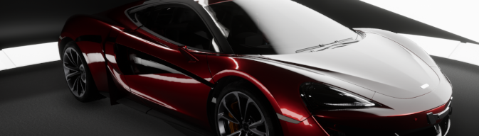
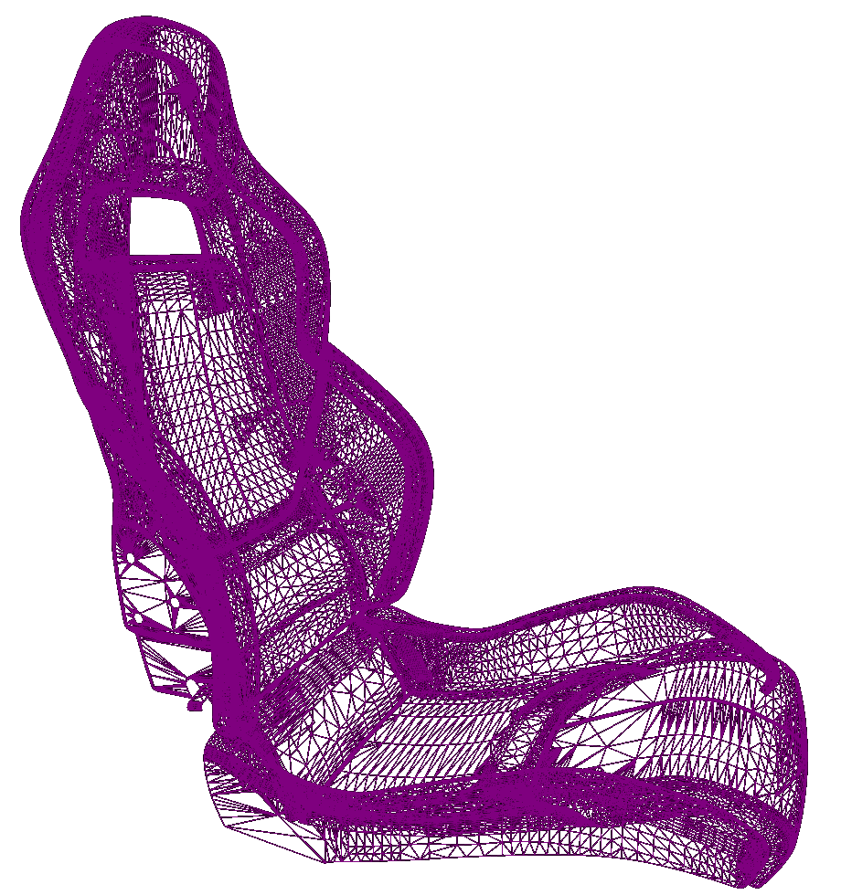
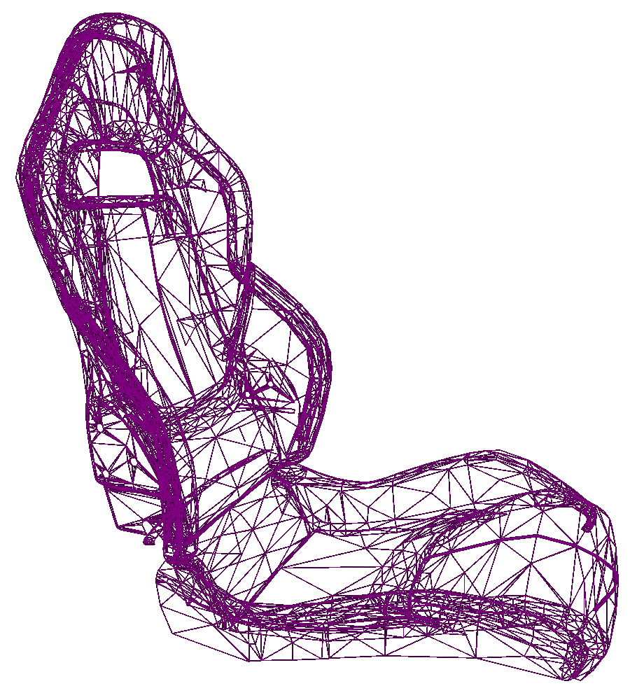
For example, the image on the left shows a surface rendered in a native CAD viewer. The image on the right shows a wireframe of a triangular mesh that was generated for that surface.


Tessellating a surface for real-time rendering involves an implicit tradeoff between the accuracy of the surface and the speed that it can be rendered.
By nature, a triangular mesh can never exactly match the mathematically precise surface it was generated from. Tessellation always implies sampling the original surface at some level of detail to create an approximation that allows the GPU to render the geometry more quickly. Typically, the closer your mesh is to the original surface, the more complex it will be — that is, it will contain more triangles, and those triangles will be smaller. This may look better when it's rendered, but places higher demands on the GPU. If you lower the accuracy of your tessellated mesh, so that it contains fewer, larger triangles, the GPU will be able to render it faster, but that rendering may not give you the visual fidelity you're looking for — it may look blocky or jagged.
Therefore, your goal in the tessellation process is to minimize the number of triangles in your mesh, while maximizing its visual fidelity to the source. This usually means that you aim to have a relatively small number of larger triangles in places where the surface is smoother and flatter, and a relatively large number of smaller triangles in places where the surface is more complex and uneven.
Datasmith offers three parameters that you can adjust when you import a CAD scene, described in the following sections. By tweaking these values, you can control the complexity and fidelity of the Static Mesh geometry that Datasmith creates for your curved surfaces.
You can also override these same options for individual Static Mesh Assets. This allows you to set overall tessellation values for your scene, then override those settings for individual objects that need higher or lower levels of detail. For details, see Retessellating CAD Geometry .
Chord Tolerance
The chord tolerance, sometimes called the chord error or sag error, defines the maximum distance that any point on the tessellated surface can be from the corresponding point on the original surface.

Lowering the value of this parameter makes the tessellated surface stay closer to the original surface, producing more small triangles.
The effect of this setting is most visible in areas with greater curvature: as the tolerance value increases, the generated triangles become larger and the surface smoothness is reduced.
|
|
|
|
|
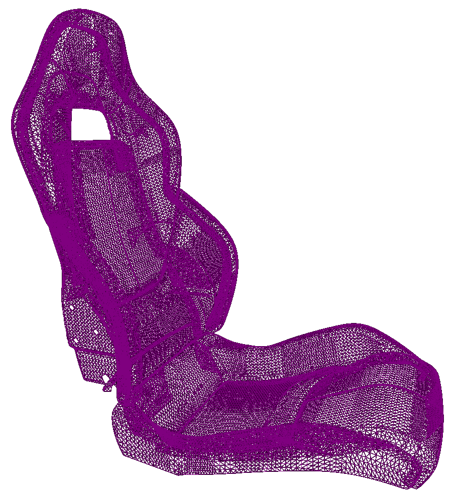
0.5mm: 37 500 triangles |
0.5mm: 37 500 triangles |
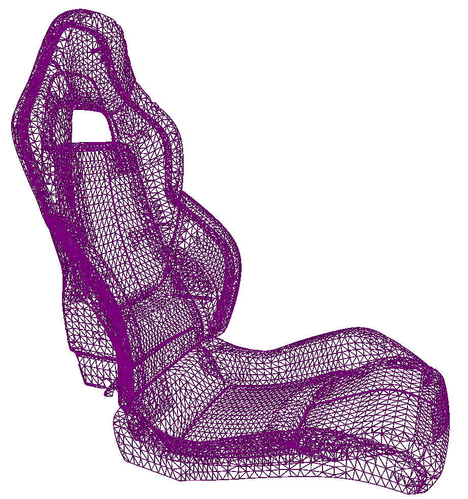
10mm: 13 500 triangles |
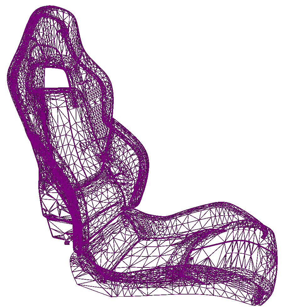
Max Edge Length
This setting limits the maximum length of any single edge in any triangle in the tessellated mesh.

The effect of this setting is most visible in flatter areas of the model. If you set this value too low, you may see that these flat areas have more small triangles than they really need. On the other hand, if you set this value too high or don't set a limit, you may sometimes get oddly shaped triangles that are extremely long and thin, which are also best avoided.
If you set this value to 0, Datasmith does not limit edge lengths in its generated triangles.
|
|
|
|
|
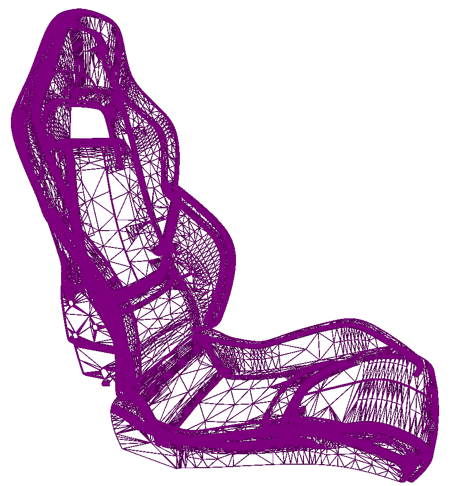
10mm: 128 000 triangles |
20mm: 43 700 triangles |
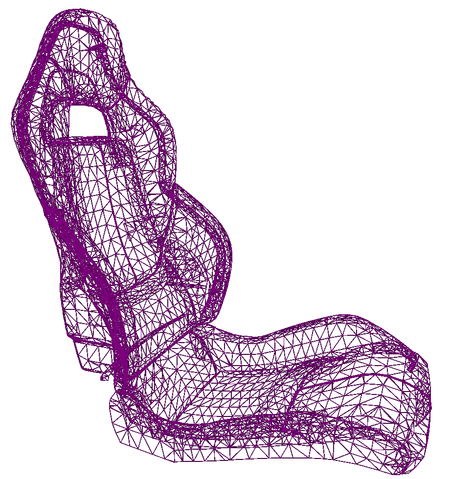
40mm: 21 000 triangles |
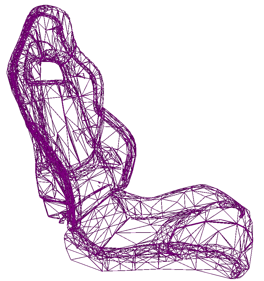
Normal Tolerance
This setting defines the maximum angle, in degrees, between any two adjacent triangles in the tessellated mesh.

Like the chord tolerance, the normal tolerance has an effect on how closely the tessellated mesh follows the original surface. However, it is particularly useful to preserve the level of detail in areas with high curvature, while having little effect on the triangles generated in flatter areas of the surface.
|
|
|
|
|
5°: 295 000 triangles |
10°: 100 000 triangles |
40°: 21 500 triangles |

Stitching Technique
The Stitching Technique setting controls how the tessellation process handles parametric surfaces that appear to be connected, but that are actually modeled as separate bodies, or as separate surfaces within a body.
-
Stitching Sew looks for surfaces that should be connected, and combines their bodies into the same Static Mesh Asset. This option may reduce the number of separate Static Mesh Assets that Datasmith creates in your Project, but takes longer to process.
Datasmith may use different strategies to test for surfaces that it should stitch together. For most types of source files, it tests for connectivity between the surfaces of nearby bodies, and merges any bodies whose surfaces are connected. For other types of files, it uses the scene hierarchy as a hint to determine connected surfaces.
-
Stitching Heal does the same, but only re-connects surfaces that belong to the same body in the source scene. If Datasmith detects that the geometry of separate surfaces within the same body should be connected, it will merge those surfaces into the same mesh element in the Static Mesh Asset that it creates. However, with this setting enabled, Datasmith will never combine multiple separate objects from the source scene into a single Static Mesh Asset.
-
Stitching None skips the stitching process completely. Datasmith always creates a separate Static Mesh Asset for each separate body in the source scene. For each of those bodies, Datasmith creates a separate mesh element in the Static Mesh Asset for each surface that the body contains.