Choose your operating system:
Windows
macOS
Linux
This Quick Start page shows the process of setting up a project in Unreal Engine to work with in-camera VFX. At the end of this guide, you will:
-
Have a synchronized cluster of nDisplay nodes.
-
Have an inner and outer frustum for in-camera VFX.
-
Have a real-time camera tracking system integrated via Live Link XR.
-
Have a green screen inner frustum with chroma key markers that can be toggled on.
-
Be able to launch all clustered nodes and test on set.
Step 1 - Set up Your Project for In-Camera VFX
The easiest way to set up an in-camera VFX project is to use the In-Camera VFX Example project.
-
Open the Epic Games Launcher .
-
In the Learn tab, find the In-Camera VFX Example project.
-
On the project page, click Free .
-
Click Create Project .
-
Specify the location on your machine to save the project and select Create .
-
Launch Unreal Engine and open the In-Camera VFX Example project.
In the example project, under Content > Maps , there are two levels, Main and EmptyStage . For learning about in-camera VFX with Unreal Engine, open the Main level. For starting with a clean setup, use EmptyStage as the base for your project. The example project and levels automatically enable the necessary plugins, provide helpful blueprints, configure additional settings, and include sample configuration files.
Plugins
-
Aja or Blackmagic Media Player: Provides support for SDI capture cards.
-
Camera Calibration A tool for creating lens distortion profiles and nodal offsets.
-
Color Correct Regions: Color correction and shading constrained to a volume.
-
ICVFX: A plugin that enables a base suite of in-camera VFX plugins.
-
Level Snapshots: Store alternative layouts for convenient, non-destructive variations of the current level with filtering abilities.
-
Live Link: Unreal Engine's API for ingesting live data, such as motion capture and camera tracking.
-
Live Link Over nDisplay: The primary node receives Live Link data and redistributes the tracking data in an efficient and synchronized manner.
-
Live Link XR: Unreal Engine's API for ingesting live data from XR devices, such as Vive Trackers.
-
Multi-User Editing: Multiple editors can be in a shared session.
-
Media Framework Utilities: Utility plugins related to live video, timecode, and genlock on SDI capture cards.
-
nDisplay: Unreal Engine's technology for rendering on multiple displays.
-
nDisplay Support for Level Snapshots: Enables support for saving and restoring nDisplay Root Actor properties with Level Snapshots.
-
OpenColorIO (OCIO): Provides support for OpenColorIO.
-
OSC: Provides functionality to send and receive OSC messages between remote clients or applications.
-
Remote Control API: A suite of tools to control the Engine remotely through a REST API, WebSockets, and C++.
-
Remote Control Web Interface: Provides a remote web interface and UI builder for remotely controlling the Editor.
-
Switchboard: Application for launching instances of Unreal, nDisplay nodes, and other Virtual Production devices in a multi-user session.
-
Timed Data Monitor: Utilities to monitor inputs that can be time synchronized.
-
Virtual Production Utilities: Utility plugins useful for Virtual Production.
nDisplay Root Actor
The nDisplay Config Asset defines the relationship between the computers in the nDisplay cluster and the topology of the LED volume. The nDisplay Root Actor is an instance of the nDisplay Config Asset in the level, and is created by dragging the nDisplay Config Asset into the level.
Sample nDisplay Config Assets are included in the example project. You can find them in the Content Browser under nDisplayConfigs. For more information on the settings exposed in the nDisplay Root Actor, refer to nDisplay Root Actor Reference .
Step 2 - Create LED Panel Geometry
This section provides an example of how to create a representation of a curved LED wall. Each LED Volume can be different, so modify these steps to match the dimensions and layout of your display.
These steps show how to create the geometry to represent the real-world LED panels.
In this example, a curved wall is created with two meshes. Each mesh is mapped to an nDisplay viewport. There are a few factors which define how an LED stage should be separated into meshes:
-
Angle: The maximum ideal angle of curvature should be 90 degrees per mesh. A curve greater than 90 degrees per mesh can cause visual degradation. In addition, no single viewport (and therefore mesh) can cover more than 179 degrees.
-
Resolution: UHD (3840 x 2160) is a sensible upper limit to render on a single GPU nDisplay viewport. For machines with multiple GPUs, you can have multiple viewports that span across a larger display resolution. Either way, separate your stage mesh based on the resolution of the LED panels in increments of the maximum resolution at which you want each machine and viewport to render. Refer to your LED manufacturer for details on your per-panel resolution.
-
Control: You might want to separate control between the ceiling and side walls, if you only use ceiling panels for lighting and reflections and they never appear in-camera. This is especially true if the LED panels are different models and require different color management. Color management is controlled per viewport, so you must break out these different panels into their own meshes.
These are considerations for how to separate the topology into meshes (and therefore viewports). It is common for a single machine to render multiple viewports, such as a ceiling and a wall. The important thing is that they are separate viewports on the single node.
Each mesh should have two UV sets in a particular order. The first UV set is used for calculating the projection for the PICP_Mesh projection policy for nDisplay. The second UV set is used to ensure that the chroma key tracking markers move appropriately across seams between two viewports.
Each square on this example mesh represents an LED panel that is 500mm x 500mm with 2.6mm pixel pitch.
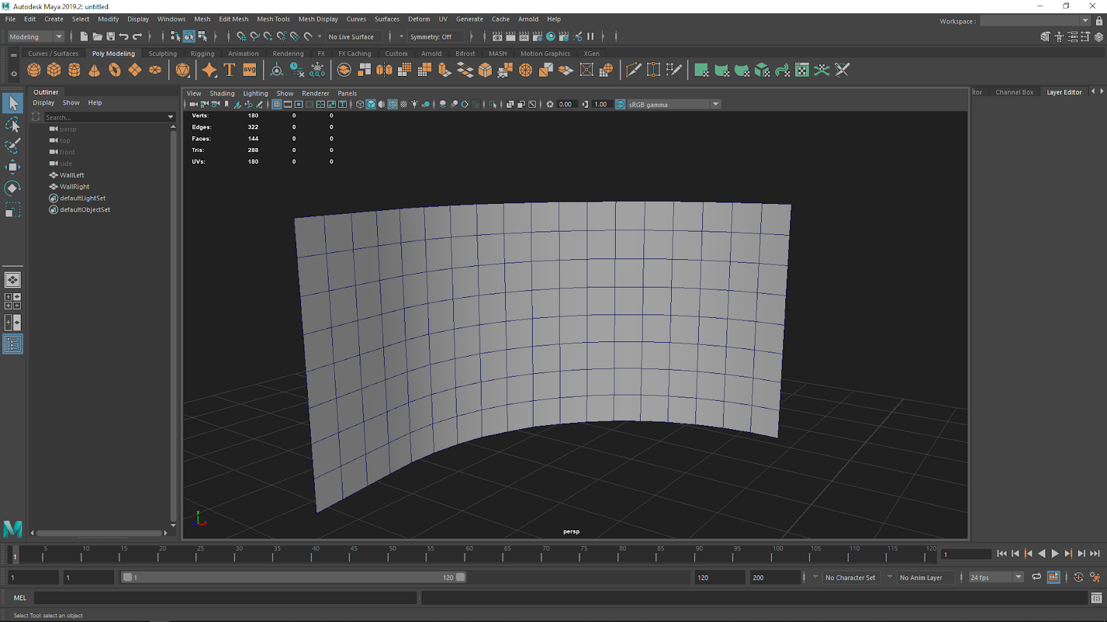
Mesh representation of a curved LED wall. Click image to enlarge.
The meshes should be modeled in a position and orientation to match the real-world LED panels. In this example, they are modeled upright. The geometry should be modeled to scale in cm.
Create the UV sets with the following specifications:
-
The first UV set should be scaled to cover the entire UV space in the range 0-1. This UV set should be unfolded as evenly as possible to avoid stretching. The scaling can be non-uniform. Ensure there is no padding around the edges of the UVs, and that the UVs do not go beyond the range 0–1.
![First UV set for the mesh]()
-
The second UV set should have the UVs aligned so that they match at the same seams as the actual hardware configuration. They should also have the same aspect ratio as the meshes.
![Second UV set for the mesh]()


When the meshes are created, export the geometry from the 3D modeling software and import them into the Unreal project. Download this example mesh and drag the file to the Content Browser into the Content/nDisplayConfigs/Meshes folder to follow the steps in the next section.
Once the meshes are imported into your Unreal Project, enable Use Full Precision UVs on each mesh to prevent UV artifacts appearing. Follow these steps for each imported mesh:
-
Double-click the imported mesh to open it in the Static Mesh Editor.
-
In the Details panel under LOD 0 , expand Build Settings and enable Use Full Precision UVs .
![Enable Use Full Precision UVs in the Details panel]()
-
Click the Apply Changes button.
![Apply Changes]()
-
Click Save .
-
Close the Static Mesh Editor.


Step 3 - Define the LED Screens in Your Project
You will need to customize the layout and geometry of the screens in the project to reflect what you have on set. These meshes should be in the same physical position and dimensions as your LED wall in the real world in relation to your tracking system. The tracking system used on set will have a zero point. These meshes should be placed in the same world coordinates as they relate to the tracking system. Work with your tracking provider to find out where the zero point is and measure relative to this zero point to find the offsets.
These examples do not use the loopback address 127.0.0.1, because its use cannot be combined with other non-loopback addresses, such as those belonging to other machines, in the same Switchboard configuration. Loopback may be used, but only in a simple configuration where it is the only address used, and every device is local to the machine running Switchboard. Mixing loopback and non-loopback addresses in a multi-machine setup leads to connectivity errors.
Follow these steps to modify and customize the layout and geometry of the screens in the engine:
-
In the Content Browser , navigate to the nDisplayConfigs folder.
-
Right-click in the folder to open the Create Asset menu and choose nDisplay > nDisplay Config .
![nDisplay Config in the Create Asset menu]()
-
In the Pick a starting point for your nDisplay Config window that appeared, choose Create New Config and click Finish .
![Create New Config]()
-
Name the new nDisplay Config Asset NDC_ICVFXQuickStart .
![Name the new nDisplay Config Asset]()
-
Double-click the NDC_ICVFXQuickStart Asset to open it in the nDisplay 3D Config Editor .
![Open the new Asset in the nDisplay 3D Config Editor]()
-
In the Components panel, right-click the nDisplayScreen Component and select Delete to remove the component from the list.
![Delete nDisplay Screen Component]()
-
Click Add Component and add two Static Mesh Components to the Components panel.
![Add two Static Mesh Components]()
-
Name one of the Static Meshes CurvedWall_Left , and in its Details panel assign ExampleCurvedWallMesh_nDisplay_WallLeft to its Static Mesh parameter. Name the other CurvedWall_Right , and assign ExampleCurvedWallMesh_nDisplay_WallRight to its Static Mesh parameter.
![Name the Static Meshes]()
-
Select both Static Mesh Components and rotate them so they're curving towards the View Origin Component. You will not see a preview of the projections on the meshes until Projection Policies have been set in a later step.
![Place and rotate the Static Mesh Components]()
-
In the Cluster panel, click the Add New button and choose Add New Cluster Node .
![Add New Cluster Node]()
If you are using the NVIDIA Quadro Sync II with NVIDIA Quadro GPUs, select the Cluster item in the Cluster panel and set Type to Nvidia (2) .
![Set Cluster Type to Nvidia 2]()
-
A Cluster Node represents a host computer. In the Add New Cluster Node window that appears:
-
Set Host IP Address to your computer's external IP address. You must use your computer's external IP address instead of the default localhost IP address 127.0.0.1, if you want to add more computers to your nDisplay cluster later, because you cannot use both loopback and non-loopback addresses in a multi-machine setup. These steps use the IP address 192.0.2.0 as an example.
-
Enable Fullscreen to achieve synchronization and genlock.
-
Click Add .
![Setting the Host IP Address]()
-
-
A Cluster Node is created and a new viewport is assigned to the node. Select the viewport in the Cluster panel to open its Details panel.
![Select the viewport in the Cluster panel]()
-
In the Details panel, set View Origin to DefaultViewPoint . This allows the associated component to control the point of projection for the outer frustum.
![Set View Origin to Default View Point]()
-
Under the Projection Policy section of the Details panel for the viewport, set Type to Mesh and select your CurvedWall_Left mesh from the list. Only Static Mesh Components added to the Components panel will show in the mesh list.
![Set Projection Policy Type to Mesh and select a mesh]()
-
See the test scene appear on the mesh in the viewport and in the Output Mapping panel.
![Set the test scene]()
-
Create a viewport for the other wall mesh. Right-click the Cluster Node and choose Add New Viewport .
![Add a new viewport]()
-
In the Add New Viewport window that appears:
-
Set View Origin to DefaultViewPoint .
-
Under Projection Policy , set Type to Mesh .
-
Under Projection Policy , set Mesh to CurvedWall_Right .
-
Click Add .
![Setting up the other wall mesh viewport]()
-
-
A second viewport is created and the test scene appears on the wall mesh in the viewport and in the Output Mapping panel.
![The second viewport]()
-
In the Components panel, add an ICVFXCamera Component. This component will give you inner-frustum controls and capabilities.
![Add an in-camera VFX camera component]()
-
Select the created ICVFXCamera Component and manipulate it within the Preview Viewport . You will see an inner-frustum projection preview on your projection meshes.
![The inner-frustum projection preview]()
-
Compile and Save the asset.
-
Drag the NDC_ICVFXQuickStart Asset into the level to create an nDisplay Root Actor and preview the level in the cluster.
![Creating the nDisplay Root Actor]()
-
Save the project.


This section showed how to create your own nDisplay Config Asset and set it up with the previously created meshes. An example nDisplay Config Asset is already included in the project with a quad mesh layout. You can find this asset in the Content Browser at nDisplayConfigs/nDisplayBasicExample .
Step 4 - Launch Your Project with Switchboard
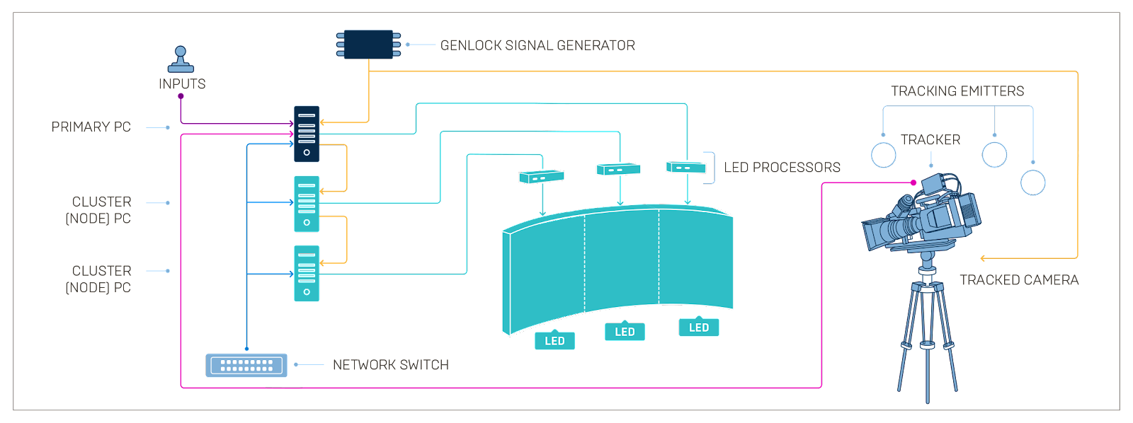
Diagram shows how nDisplay works with a network and display devices for in-camera VFX. Click image to enlarge.
In an nDisplay setup, there is a primary computer and a cluster of additional computers. The primary computer is the centralized location for managing and dispatching input information. The primary computer also ensures all PCs in the cluster are synchronized and receive input and data at the same time. For more information on an nDisplay setup, see nDisplay Overview .
Switchboard is an external application that allows a single operator to control nDisplay clusters. Switchboard has additional features such as advanced logging, system monitoring, and integration with external software to simultaneously trigger third-party motion capture software take recording with Take Recorder .
Follow the steps below to launch the nDisplay cluster with Switchboard:
-
In the toolbar, click the Switchboard button. If this is your first time launching Switchboard, a command prompt appears and installs required dependencies.
![Launch Switchboard]()
-
In the toolbar, click the arrow next to the Switchboard button and in the dropdown menu choose Launch SwitchboardListener . This companion application must be run on every machine in the cluster to be able to connect to Switchboard.
![Launch Switchboard Listener]()
-
Create a new Switchboard Configuration for the project.
-
If this is your first time running Switchboard, the Add New Switchboard Configuration window appears when Switchboard launches.
-
If you have run Switchboard before, click Configs > New Config in the top left corner of the window to open the Add New Switchboard Configuration window.
-
-
In the Add New Switchboard Configuration window:
-
Set Config Path to ICVFXQuickStart .
-
Set uProject to the location of the In-Camera VFX Example Project on your computer.
-
Set Engine Dir to the location of Unreal Engine 4.
-
Click OK .
![Add a new Switchboard config]()
-
-
In Switchboard, set Level to Main .
![Set Switchboard Level to Main]()
-
Click Add Device > nDisplay to open the Add nDisplay Device window.
![Add an nDisplay device]()
-
In the Add nDisplay Device window, click the Populate button to see a list of available nDisplay Config Assets from the project. Select the nDisplay Asset created in the previous section, NDC_InCameraVFXQuickStart , and click OK .
![Add the QuickStart Asset]()
-
The cluster node appears under nDisplay Devices .
-
Click its Connect to listener button to connect to the Switchboard Listener.
![Click Connect to listener on the new node]()
-
Click its Start Unreal button to launch Unreal with the nDisplay renderer.
![Start Unreal button]()
-
-
When nDisplay launches, all windows are minimized on the computer and the nDisplay view appears.
![The nDisplay sample project]()


Step 5 - Join Multi-User Session
The Multi-User Editing system enables robust collaboration to support any type of change. Multiple operator machines in the same Multi-User session can perform different tasks and modify the scene in real-time. In an nDisplay setup, Multi-User is responsible for synchronizing changes across the various instances of Unreal Engine on the cluster nodes to ensure that creative updates to the scene appear immediately and simultaneously on the LED wall during a shoot.
Follow the steps below to connect your Unreal Editor to the nDisplay renderer through Multi-User.
-
In Switchboard, click the Stop Unreal button on the nDisplay node.
![Stop Unreal button]()
-
Click the Settings button to open the Switchboard Settings window.
-
Under the Multi User Server section:
-
Set Server Name to ICVFXQuickStart_MU_Server .
-
Enable Auto Join so any Unreal instances or nDisplay nodes automatically attempt to connect.
-
Enable Auto Launch . The Multi User Server Executable will not start without it enabled.
![The Multi User Server settings]()
-
-
Close the Settings window.
-
Set Multiuser Session to ICFVXQuickStart_Session_001 .
![Set the multi user session]()
-
Click the Start Unreal button next to the nDisplay node to relaunch it.
![Start Unreal button]()
-
Wait for the nDisplay node to finish launching before going to the next step.
-
In the Editor's Toolbar , click the Browse button to open the Multi-User Browser .
![Browse button in the Toolbar]()
-
In the Multi-User Browser , double-click ICVFXQuickStart_Session_001 to connect your Unreal Editor to the multi-user session started with nDisplay.
![The Multi User Browser]()
If the Unreal Editor displays a message about in-memory changes and prevents you from joining your multi-user session, it means that something in your editor may have an unsaved change and your project doesn't match the current state of the project running with nDisplay. All projects joining a multi-user session should be in the exact same state. To fix this, make sure to save the project before launching nDisplay.
-
The Multi-User Browser will now change to show you the session you are currently connected to and the Level each user has active. The Clients category will show you which nodes and Editor instances are connected. History will list transactions that have been made over a Multi-User session. Details will show more information about the currently selected transaction in the History category.
![The categories of the Multi User Browser]()
-
Changes you make in the Editor are now transmitted to the nDisplay node. Move the Default View Point Component for NDC_ICVFXQuickStart to see the nDisplay view update with the changes in the Editor.
![Changes to view origin in Unreal Editor transmitting over multi-user to nDisplay render]()


Step 6 - Use Live Link for Camera Tracking
Live Link is a framework in the Unreal Engine for ingesting live data, including cameras, lights, transforms, and basic properties. For in-camera VFX, Live Link plays a critical role in distributing the tracked camera information and can be enabled to work with nDisplay to carry the tracking information to each cluster node. Unreal Engine supports many camera-tracking partners through Live Link, such as Vicon, Stype, Mo-Sys, and Ncam, as well as several other professional tracking solutions. Live Link also supports XR devices such as Vive Trackers and Controllers as a Live Link source.
It's important for this step that you have a Live Link source available. This guide will show how to set up Live Link XR in your project so you can use a VR headset and controllers for tracking. You can use similar steps to enable other Live Link sources. Refer to Live Link XR for more details.
To track the inner camera frustum via Live Link XR with nDisplay:
-
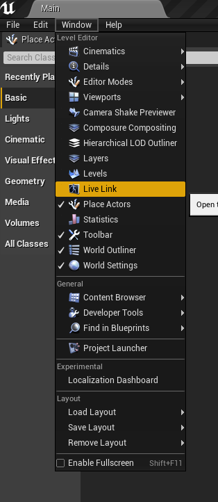
In Unreal Editor's main menu , choose Window > Live Link to open the Live Link panel.
![The editor with Live Link highlighted in the Window dropdown]()
-
In the Live Link panel, click the Add Source button. In the dropdown, choose Live Link XR Source .
-
In the Connection Settings panel that appears, enable Track Controllers and Track HMDs and click Add .
![The connection settings]()
-
When the Live Link XR Source is added, connected XR devices appear under the XR section of the Subject panel.
![Connected XR devices]()
-
In the Subject panel, select the XR device you're using for tracking to open its Details panel. In the Details panel, enable Rebroadcast Subject to share the tracking data with other computers in the Multi-User Session.
![Live Link Subject with the property Rebroadcast Subject enabled]()
-
Click Presets and select Save as Preset .
-
In the main menu, select Edit > Project Settings .
-
In Project Settings, under Plugins , select Live Link .
-
Add the Live Link preset to Default Live Link Preset to make the preset automatically apply when the project runs.
![Set the Default Live Link Preset]()
-
In the World Outliner , select DemoDisplay3_innerFrustum to open its Details panel.
-
Click Add Component and choose Live Link Controller to add a Live Link Component Controller to the Cine Camera Actor.
-
In DemoDisplay3_innerFrustum 's Component section, select LiveLinkComponentController to view its settings.
-
Under Live Link , set the Subject Representation parameter to your Live Link Subject. In this example, the Live Link Subject is a SteamVR Controller.
![Set the Live Link Subject Representation]()
-
Select the ICVFX Camera Component of the NDC_ICVFXQuickStart Actor to open its Details panel. Set Cine Camera Actor to DemoDisplay3_innerFrustum.
![Set the Cine Camera Actor]()
-
When you move the XR device, the camera in the editor mimics the movement. The inner frustum also appears in the nDisplay preview when the camera faces the meshes.
![Camera tracking in the sample]()
-
Save the project.
-
Restart the nDisplay cluster to see the changes in the nDisplay renderer.


Step 7 - Enable Green Screen and Chroma Key
You can change what displays in the inner frustum on the LED panels from the virtual world to a green screen with chroma key markers.

Follow these steps to make the green screen visible and to modify the chroma key markers:
-
In the World Outliner, select NDC_ICVFXQuickStart .
-
In the Details panel, select the ICVFXCamera Component to view its settings.
-
In the Details panel under Chromakey , enable Enable Inner Frustum Chromakey .
![Enable inner frustum chromakey]()
-
The inner frustum turns green and tracking markers are rendered on top.
![Inner frustum showing tracking markers]()
-
Change the parameters in the Chromakey section to modify the color, marker placement, and custom marker alpha textures. For more details on the settings, refer to nDisplay Root Actor Reference .
![Changing the chromakey placement]()


This section showed how to enable chroma key for the inner frustum. An example nDisplay Config Asset with chroma key enabled is already included in the project with a quad mesh layout. You can find this asset in the Content Browser at nDisplayConfigs/nDisplayExample_Chromakey .
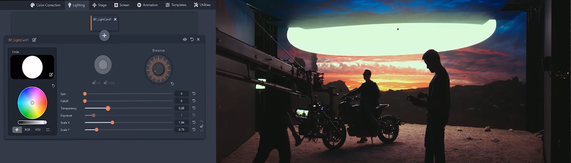
Step 8 - Add Light Cards
Light Cards can be found in the nDisplay plugin content. Light Card Actors should be spawned to a separate layer to take advantage of nDisplay's Light Card control features and parented to the Config Actor's outer frustum viewpoint for optimum effect.
Follow the steps below to add Light Cards to your project.
-
In the Content Browser , click View Options and enable both Show Engine Content and Show Plugin Content .
![View Options for the Content Browser]()
-
In the Sources panel, open the nDisplay Content/LightCard folder.
![Open the nDisplay Content Lightcard folder]()
-
Drag the Blueprint LightCard into your level. In the World Outliner , parent the LightCard actor to NDC_ICVFXQuickStart .
![Dragging a Lightcard into the level]()
The splines visualise the position of the lat/long location of the Light Card. For a better projection to the outer frustum, place the Light Card Actor in the same location as the View Origin Component in the nDisplay Root Actor.
-
In the main menu, choose Window > Layers to open the Layers panel.
![The Layers panel]()
-
In the Layers panel, right-click and choose Create Empty Layer from the dropdown. Name the Layer ICVFXQuickStart_LightCards .
![Create and name a Layer]()
-
In the World Outliner , select the Light Card . Right-click the ICVFXQuickStart_LightCards layer and choose Add Selected Actors to Selected Layers .
![Add Lightcard Actors to the Layer]()
-
In the World Outliner , select NDC_ICVFXQuickStart to open its Details panel.
-
In the Details panel under Light Cards , add an Array element to the Layers parameter.
![Add an Array element to the Layer]()
-
Set the Layer Array element to ICVFXQuickStart_LightCards .
![Set the Layer Array element to your Lightcard]()


For more details on the Light Card settings, refer to nDisplay Root Actor Reference .
Step 9 - Shoot with Multi-Frustum
Multiple inner frustums can appear in the nDisplay Config Asset. In this step we'll add a second ICVFXCamera component to the NDC_ICVFXQuickStart nDisplay Config Asset and set it up for multi-frustum shooting.
Follow the steps below to add another ICVFX Camera Component to the nDisplay Config Asset.
-
Stop all nDisplay nodes before the next step.
-
In the Content Browser , double-click the NDC_ICVFXQuickStart Asset. Currently, there will already be an ICVFXCamera Component present in the Components panel.
![Open the Camera Component]()
-
Click Add Component and add another ICVFXCamera Component. Ensure both are parented to the Root Component in the Component hierarchy. Name the two ICVFXCamera Components as follows:
-
ICVFXCamera_ACam
-
ICVFXCamera_BCam
![Naming the cameras]()
-
-
Select the new ICVFXCamera component and manipulate it in the viewport to see the multiple frustum projections.
![Manipulting the multiple frustums]()
-
Compile and Save the nDisplay Config Asset.
-
The nDisplay Root Actor created from this Asset automatically is updated with the second camera in the level.
-
In the World Outliner , select NDC_ICVFXQuickStart to open its Details panel. In the Details panel under In-Camera VFX , expand Inner Frustum Priority and change the order of the cameras. The camera listed first is rendered on top of the other when they overlap.
![Demonstrating frustum priority]()
-
Add a new CineCamera Actor to your level to reference it from the ICVFXCamera component. Add a LiveLinkComponentController to the new CineCamera Actor and connect a Live Link Subject to the Component.


This section showed how to add another camera with its own inner frustum to the nDisplay Config Asset. An example nDisplay Config Asset with two cameras is already included in the project with a quad mesh layout. You can find this asset in the Content Browser at nDisplayConfigs/nDisplayExample_multiFrustum .
Step 10 - Apply OpenColorIO Configuration
This section shows how to create an OCIO Configuration Asset from a plugin content OCIO config file and assign it to the nDisplay Root Actor viewports.
Follow these steps to use an OCIO configuration in the project:
-
In the World Outliner , select NDC_ICVFXQuickStart to open its Details panel.
-
In the Details panel under OCIO , check Enable Viewport OCIO .
-
Expand All Viewports Color Configuration .
-
Set Configuration Source to ExampleOCIO .
-
Set Source Color Space to Utility - Raw .
-
Set Destination Color Space to Output -sRGB Monitor .
-

These steps showed how to add an OCIO configuration to the project. You can also set OCIO configurations per viewport and separately on the inner frustum. For more on how to do this, refer to Color Management in nDisplay .
Step 11 - Control the Scene Remotely
The Remote Control Web Interface is a customisable web application that utilises the Remote Control API . This section shows how to create a Remote Control Preset and make changes to your level from a web browser interface.
Follow the steps below to create your own Remote Control Preset and Remote Control Web Application.
-
In the Content Browser , right-click and choose Miscellaneous > Remote Control Preset to create a new Remote Control Preset Asset.
![Create a new Remote Control Preset]()
-
Double-click the Remote Control Preset Asset to open the Remote Control Panel .
![The Remote Control Panel]()
-
In the Remote Control Panel , enable Edit Mode to show Closed and Open Eye buttons next to properties in the Details panel.
-
In the World Outliner , select the actor WebControlMannequinStatic to open its Details panel.
-
In the Details panel under the Transform section, click the Expose button to expose the Location and Rotation properties to the Remote Control API.
![Expose the Locaton and Rotation properties to the Remote Control API]()
-
In the Remote Control Panel , click the Edit button next to Default Group in the Control Panel window and name the group of properties Mannequin Transforms .
![Name the group]()
-
In the Remote Control Panel , click the Launch Web App button to launch a web browser that will connect to the Remote Control Web Application . On your local computer, the web app is accessible at 127.0.0.1:7000 .
![Launch the web browser to connect to the Remote Control Web Application]()
-
In the Remote Control Web Application , switch the Control toggle to Design mode.
![Toggle between Control and Design]()
-
Select the Properties tab.
-
Click and drag Relative Location to the empty canvas. A blue circle in the Properties tab appears next to the property when a property has been added to the interface.
![Click and drg the Relative Location widget]()
-
Click and drag Relative Rotation to the same canvas.
-
Select the Relative Location Widget in the canvas to open its settings.
-
In the widget settings for Relative Location , set Widget to Joystick to change the look of the widget.
![Set the widget to joystick]()
-
Select the Relative Rotation Widget to open its settings.
-
In the widget settings for Relative Rotation , set Widget to Sliders .
-
Toggle from Design mode to Control mode to lock the interface.
-
With your Editor viewport visible, interact with the UI controls to see how it affects your level.
![Manipulating the Remote Control UI to affect your level]()


Step 12 - On Your Own
This guide covered setting up displays on LED screens, launching your project on multiple computers, and incorporating camera tracking into the project. Additional example nDisplay Config Assets are included in the project in the nDisplayConfigs folder that show how to set up your cluster in other configurations including with multi-node and mGPU.
Multi-display setups require syncing capabilities at both software and hardware levels. Not only should the generated content be ready at the same time on all PCs, using the same timing information for simulation, but the display swap (the changing out of the current image for the next image in the video card buffer) needs to also happen at the correct time to prevent tearing artifacts in the display. See synchronization in nDisplay for information on setting up display sync and genlock on the machines to create a seamless view across the multiple displays.
In addition to synchronizing the displays, the engine's timecode and frame generation needs to match the input from the camera. See Timecode and Genlock for steps on how to sync the timecode and genlock the engine between all the devices.
To be able to control the scene and displays during a film shoot, you can try several of the How-Tos for in-camera VFX:
-
On-stage scene modification in real-time with Multi-User Editing .
-
Live compositing using Composure .
-
Match the lighting and shadows between the real-world set and the environment displayed on the LED walls with Color Correct Regions .
-
Save and restore Actor states for each take with Level Snapshots .
-
Calibrate the display of content on your LED wall for your camera with the In-Camera VFX Camera Calibration guide.
-
Receive and monitor events from every machine in your network with Stage Monitor .
-
Monitor, calibrate, and view incoming timed data with the Timed Data Monitor .
-
Use motion blur effectively in your process shots with Camera Motion Blur in nDisplay .
-
Color correct for only the displays and inner frustum with Color Management in nDisplay .
This guide walked through the basics of in-camera VFX projects. For an example of a real production project, refer to the In-Camera VFX Production Test .