Choose your operating system:
Windows
macOS
Linux
Overview
Unreal Engine's Navigation System provides pathfinding capabilities to Artificial Intelligence Agents. To make it possible to find a path between a start location and a destination, a Navigation Mesh is generated from the world's collision geometry.
Default settings subdivide the Navigation Mesh into tiles to allow localized parts of the Navigation Mesh to be rebuilt. The resulting mesh is made of polygons with a cost assigned to each polygon. While determining the optimal path, the pathfinding algorithm will attempt to determine the path with the lowest cost to the destination.
The Navigation System includes a variety of components and settings that modify the way the Navigation Mesh is generated, including the cost of polygons. This, in turn, affects the way Agents navigate through your Level.
Goals
In this Quick Start guide, you will learn how to modify the Navigation Mesh using Navigation Modifier Volumes , Navigation Proxy Links , and Blueprint Actors that affect navigation at runtime.
Objectives
-
Use Navigation Modifier Volumes to alter the Navigation Mesh cost in specific areas
-
Use Navigation Proxy Links to create connections between two areas that are otherwise inaccessible
-
Use Smart Proxy Links to allow your Agents to jump between platforms towards their goal
-
Create moving Blueprint Actors to learn how the Navigation Mesh can be regenerated dynamically at runtime
1 - Required Setup
Follow the Modifying the Navigation System preparation guide or download the full sample project and open the LevelModNavigation_0 Level before proceeding to the next section.
2 - Using Navigation Modifier Volumes
A Navigation Modifier Volume applies a Navigation Area Class to the Navigation Mesh using a volume shape. This can be used to change the properties of the polygons within the volume space to modify their traversal cost.
The polygon properties are defined by the appropriate Area Class of the Navigation Modifier Volume. This class determines the effect on the Navigation Mesh. You can use the built-in classes to modify the mesh or create your own custom implementations.
You will now start by using the built-in classes to modify the Navigation Mesh in your Level.
-
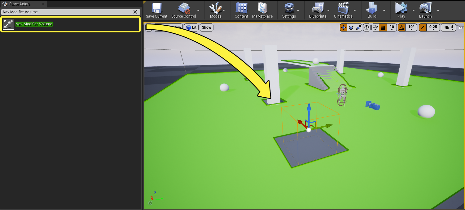
Go to the Place Actors panel and search for Nav Modifier Volume . Drag the Nav Modifier Volume Actor into your Level. Notice that by default, no Navigation Mesh is generated inside the volume.
![Mod-NavMod-Drag.png]()
-
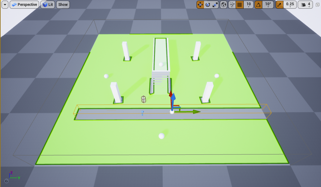
Move and scale the volume to cover the area shown below. Notice how you are now forcing the Agent to reach the bottom sphere by moving around the volume on the left side of the Level. This area could represent any obstacle the Agent is not allowed to cross in your game.
![Mod-NavMod-Null1.png]()
-
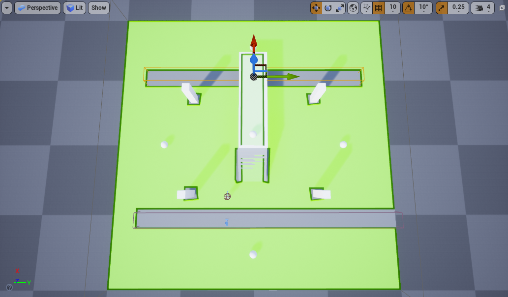
Repeat the step above and create another area on the opposite side of the map. When you scale the volume, leave space on both sides for the Agent to navigate.
![Mod-NavMod-Null2.png]()
-
Drag another Nav Modifier Volume into your Level. Navigate to the Details panel and click the dropdown next to Area Class . Select the NavArea_Obstacle class from the list. This built-in class assigns the area inside the volume a higher cost of navigation compared to the default value ( NavArea_Default in green). This will cause your Agent to avoid the area unless it cannot find a cheaper path to its destination.
![Mod-NavMod-Obs1.png]()
![Mod-NavMod-Obs2.png]()
-
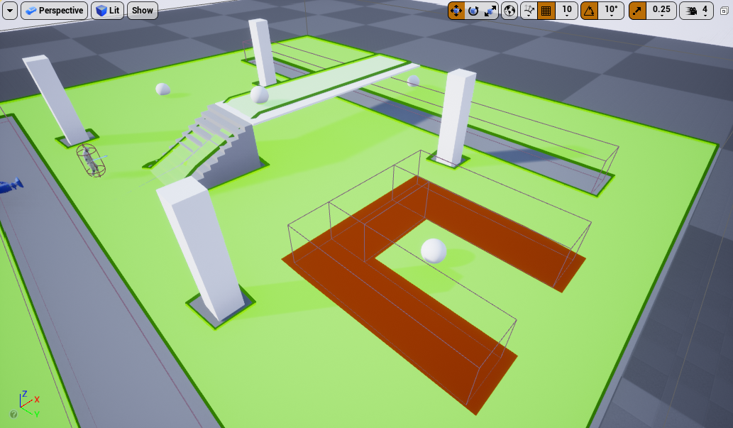
Duplicate the volume twice to form the following shape around the sphere. This will force the Agent to navigate around the volumes to reach the sphere.
![Mod-NavMod-Obs3.png]()
If you completely block the area around the sphere with another volume, the Agent will still reach its destination because the volumes represent a valid path. In contrast, if you were to change the Area Class of the volumes to NavArea_Null, the Agent will not be able to reach its destination as it will not be able to find a suitable path to its target. This is because the NavArea_Null applies an infinite cost which causes the Navigation Mesh to not be generated in the affected area.


-
Click Simulate and notice how your Agent moves between the spheres. This illustrates how your changes have affected the way the Navigation Mesh was generated.
![Mod-NavMod-Demo.gif]()
Section Results
In this section you learned how to use Nav Modifier Volumes to change the way the Navigation Mesh is generated. You also learned about some of the built-in Area Classes available in Unreal Engine.
Available Nav Modifier Volume Area Classes
|
Area Class |
Description |
|---|---|
|
NavArea_Default |
Assigns the same navigation cost to the area inside the volume and the Navigation Mesh by default. |
|
NavArea_LowHeight |
Represents an area that matches the conditions for traversal with a low height which prevents an Agent from traversing it. The Navigation Mesh will not generate navigation data inside this volume. |
|
NavArea_Null |
Represents an empty area inside the volume. The Navigation Mesh will not generate navigation data inside this volume. |
|
NavArea_Obstacle |
Assigns a high navigation cost to the area inside the volume. |
3 - Using Navigation Link Proxies
Navigation Link Proxies connect two areas of the Navigation Mesh that don't have a direct navigation path. While a path is being searched, Navigation Link Proxies are used as extra connections that Agents can use to reach their destination.
Navigation Link Proxies are commonly used to build bridges between areas with separate Navigation Meshes and to instruct Agents that they can fall or jump from a platform towards their goal when there is no continuous navigation path available.
Creating Bridges to Connect Two Areas
-
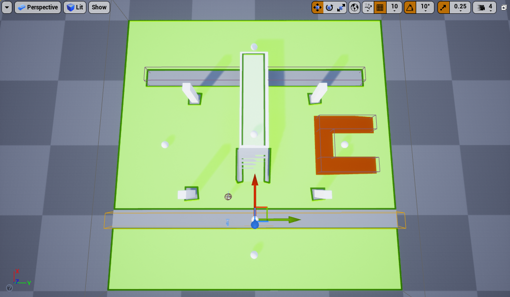
Select the first Nav Modifier Volume and resize it so it covers the entire length of the floor, as seen below. This blocks the Agent from reaching the bottom sphere in the Level.
![Mod-NavLink-NavMod-Resize.png]()
-
Go to the Place Actors panel and drag a Cube Actor into the Level. Scale it to X = 4, Y = 1, Z =0.2 and place it as shown below.
![Mod-navLink-Cube1.png]()
-
Duplicate the cube and move it to the other side of the Level, as shown below.
![Mod-navLink-Cube2.png]()
These Cube Actors serve as a visual representation of the Navigation Link Proxies in the Level. You are not required to use them in conjunction with Navigation Link Proxies.


-
Go to the Place Actors panel and search for Nav Link Proxy . Drag the Nav Link Proxy Actor into your Level.
![Mod-NavLink-Drag.png]()
-
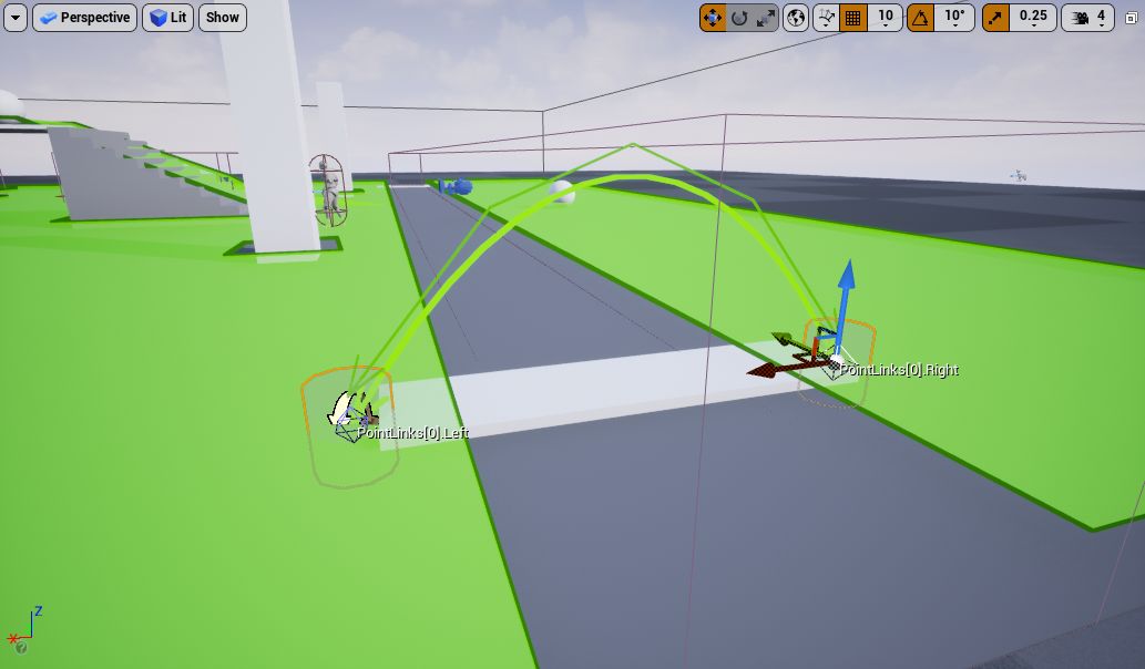
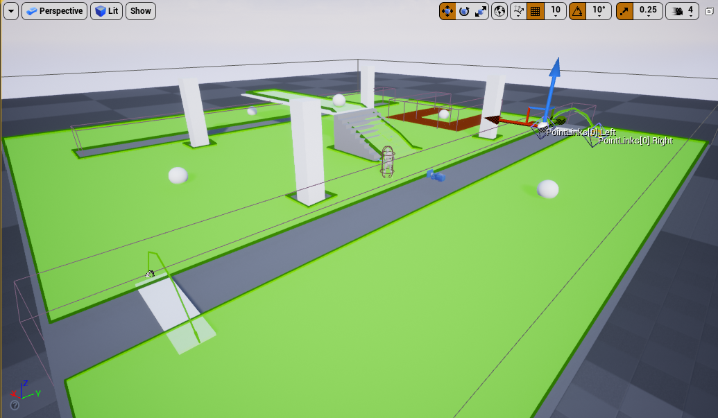
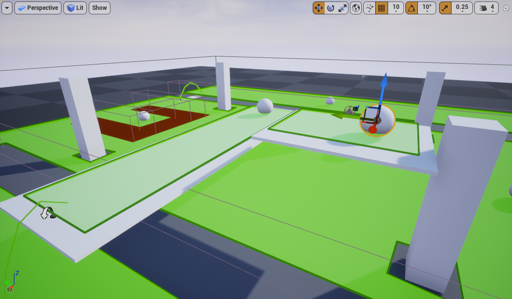
With the Nav Link Proxy selected, click the PointLinks[0]. Left handle and move it so it's placed one one side of the mesh. Click the PointLinks[0].Right handle and move it so it's placed on the opposite side of the mesh, as shown below.
The green arrow will disappear if the Nav Link Proxy doesn't connect with the surface of the Navigation Mesh.
![Mod-NavLink-Bridge1.png]()
Now that you have created a connection, the Agent will be able to navigate through the Nav Link Proxy , even though there is no navigation data in between.
-
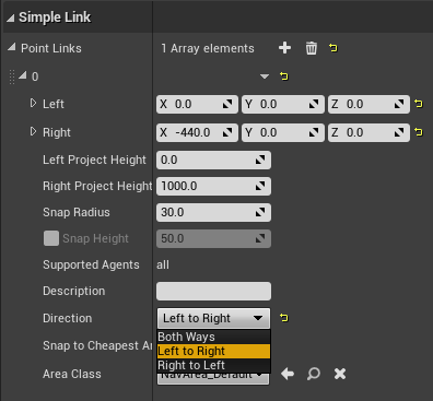
With the Nav Link Proxy selected, go to the Details panel and expand the section labelled 0 under Point Links to find the Direction dropdown. You can choose to have the Direction be Both Ways , Left to Right , or Right to Left . For this example, select Left to Right .
![Mod-NavLink-Direction.png]()
-
Duplicate the Nav Link Proxy and move it to the other side of the level. For this example, set the Direction to Right to Left .
![Mod-NavLink-Bridge2.png]()
-
Click Simulate and notice how your Agent can now reach the sphere by entering from the left side and exiting from the right side.
![Mod-NavLink-Demo.gif]()

Section Results
You used Nav Link Proxies to connect two areas of the Navigation Mesh that did not have a viable path. You also learned that you can configure the Nav Link Proxies to have different directions, such as Both Ways , Left to Right , or Right to Left .
Using a Nav Link Proxy to Allow Your Agent to Fall from a Platform
-
Drag another Nav Link Proxy into your Level and place it at the end of the raised platform, as seen below.
![Mod-NavLink-Fall1.png]()
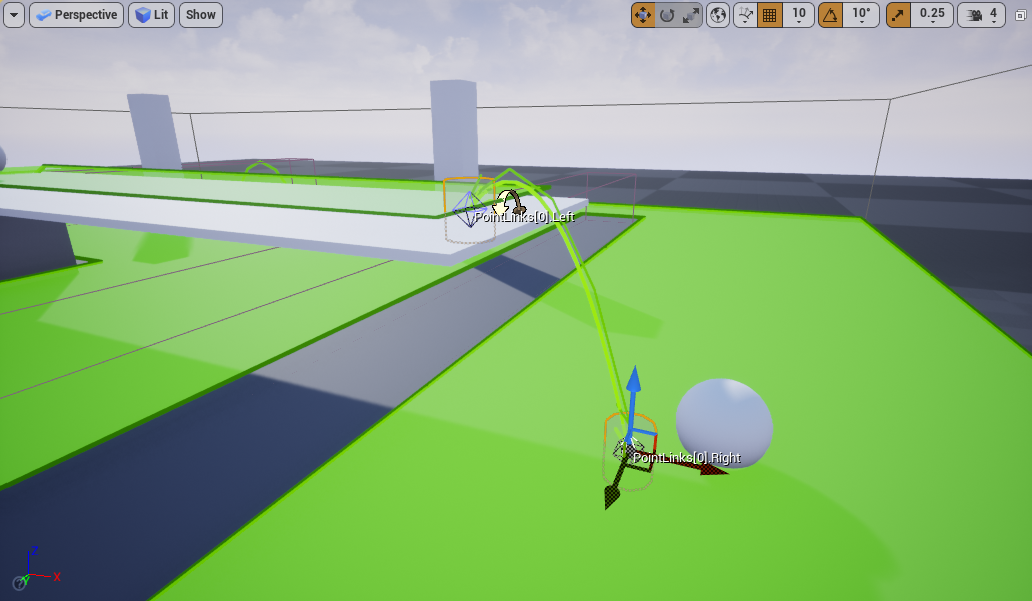
-
Select the PointLinks[0].Left and place it at the edge of the platform and select the PointLinks[0].Right and place it at the bottom overlapping the floor.
![Mod-NavLink-Fall2.png]()
-
Navigate to the Details panel, expand the section labelled 0 under Point Links and select Left to Right as the Direction .
![Mod-NavLink-Fall3.png]()
-
Click Simulate and notice how your Agent is now able to fall from the platform to reach its goal.
![Mod-NavLink-Demo2.gif]()


Section Results
In this section you used a Nav Link Proxy to allow your Agent to fall from a platform to reach its goal.
Using a Nav Link Proxy to Allow Your Agent to Jump to Its Goal
In this section you will learn how to use a Smart Link on a Nav Link Proxy to allow your Agent to jump from one platform to another.
-
Select the platform mesh and drag it while holding the Alt key to the side to duplicate it.
![Mod-SmartLink-Platform1.png]()
-
Resize the new platform and move it higher, as shown below.
![Mod-SmartLink-Platform2.png]()
-
Duplicate a Sphere Actor and place it on top of the platform.
![Mod-SmartLink-Platform3.png]()
-
Inside the Content Browser , right-click and select Blueprint Class from the Create Basic Asset section.
![Mod-SmartLink-Create1.png]()
-
Inside the Pick Parent Class window, go to the All Classes section and expand the arrow. Search for and select Nav Link Proxy and click Select . Name the Blueprint BP_NavProxyLink .
![Mod-SmartLink-Create2.png]()
![Mod-SmartLink-Create3.png]()
-
Open BP_NavProxyLink by double-clicking it. Inside the Event Graph , right-click then search for and select Event Receive Smart Link Reached .
![Mod-SmartLink-BP-Event.png]()
-
Drag from the Agent pin of the Event Receive Smart Link Reached node then search for and select Cast to Character .
![Mod-SmartLink-BP-Cast.png]()
-
Drag from the As Character pin of the Cast to Character node and select Promote to variable .
![Mod-SmartLink-BP-Character.png]()
-
Drag from the execution pin of the As Character node then search for and select Suggest Projectile Velocity Custom Arc .
![Mod-SmartLink-BP-CustomArc.png]()
-
Drag from the blue pin of the As Character node then search for and select Get Actor Location . Connect the Return Value pin of the Get Actor Location node to the Start Pos pin of the SuggestProjectileVelocityCustomArc node.
![Mod-SmartLink-BP-StartPos.png]()
-
Drag from the Destination pin of the Event Receive Smart Link Reached node and connect it to the End Pos pin of the SuggestProjectileVelocityCustomArc node.
![Mod-SmartLink-BP-EndPos.png]()
-
Drag the As Character variable into the Event Graph and select Get As Character . Drag from the node then search for and select Launch Character . Enable the XYOverride and ZOverride checkboxes.
![Mod-SmartLink-BP-LaunchCharacter1.png]()
-
Drag from the SuggestProjectileVelocityCustomArc node then search for and select Delay . Set the Duration to 0.1. Connect the Completed pin of the Delay node to the Launch Character node.
![Mod-SmartLink-BP-Delay.png]()
-
Drag from the Out Launch Velocity pin of the SuggestProjectileVelocityCustomArc node then search for and select vector * float .
![Mod-SmartLink-BP-JumpBoost1.png]()
-
Connect the yellow pin of the Multiplication node to the Launch Velocity pin of the Launch Character node. Right-click the green pin of the Multiplication node and select Promote to variable .
![Mod-SmartLink-BP-JumpBoost2.png]()
-
With the New Var 0 node selected, go to the Details panel and rename the variable to JumpBoost . Set the default value to 1 . Enable the Instance Editable checkbox, as shown below.
![Mod-SmartLink-BP-JumpBoost3.png]()
-
Compile and save your Blueprint.
![Mod-SmartLink-BP-Final.png]()
-
Select the BP_NPC_ModNavMesh character in your Level and under the Details panel, click on the Add (+) button next to Target List to add a new entry. Search for and select the last Sphere Actor you added to the platform.
![Mod-NPC-Targets2.png]()
-
Drag the BP_NavProxyLink Blueprint Actor onto the platform and adjust the connections, as seen below.
![Mod-SmartLink-BP-Drag.png]()
-
With the BP_NavProxyLink Blueprint Actor selected, go to the Details panel and click the Copy End Points from Simple Link to Smart Link button. Enable the Smart Link Is Relevant checkbox
![Mod-SmartLink-BP-Drag2.png]()
-
Click Simulate and watch as your Agent can now jump to reach the last sphere.
![Mod-NavLink-Demo3.gif]()
Nav Link Proxies can only connect adjacent Navigation Mesh tiles. You can visualize the tiles by selecting the RecastNavMesh-Default Actor and enabling the Draw Tile Bounds checkbox.


Section Results
In this section you learned how to create a custom Nav Proxy Link Blueprint and how it can be used to get your Agent to jump to a platform.
4 - Generating the Navigation Mesh at Runtime
Unreal Engine comes with three Navigation Mesh generation modes:
|
Generation Mode |
Description |
|---|---|
|
Static |
The Navigation Mesh is generated offline and is saved with the Level. The Navigation Mesh is loaded at runtime and cannot change. |
|
Dynamic |
The Navigation Mesh is generated offline and is saved with the Level or built at runtime. At runtime, the navigation-relevant data used by the Navigation Mesh can be updated and the generation is performed on the tiles affected by the change in the data. |
|
Dynamic Modifiers Only |
The Navigation Mesh is generated offline and is saved with the Level. At runtime, only Navigation Modifiers such as Navigation Areas, Navigation Links, and dynamic objects, can modify the existing Navigation Mesh by changing the cost or block areas. No new Navigation Mesh surfaces are generated at runtime. This method allows the Navigation Mesh to cache collision data, and can result in up to 50% cheaper processing of the affected tiles. Advanced users should use this mode after careful consideration of its benefits and limitations. |
By default, the Navigation Mesh is configured to be Static . However, you can set your Navigation Mesh generation to one of the dynamic modes so it can change at runtime.
Using the Runtime Generation (Dynamic Modifiers Only)
-
To change the Runtime Generation settings, go to Settings > Project Settings on the menu bar.
![Mod-Dyn-ProjectSettings1.png]()
-
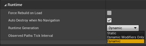
Go to the Navigation Mesh settings and under the Runtime section, click the Runtime Generation dropdown. Select Dynamic Modifiers Only for this example.
![Mod-Dyn-ProjectSettings2.png]()
-
Inside the Content Browser , right-click and select Blueprint Class under the Create Basic Asset section.
![Mod-SmartLink-Create1.png]()
-
Select the Actor class under the Common Classes section. Name the Blueprint BP_RotatingActor .
![Mod-Rot-Create.png]()
![Mod-Rot-Create2.png]()
-
Double-click the BP_RotatingActor Blueprint to open it. Click the Add Component dropdown, then search for and select Cube . Scale the Cube to X = 4, Y = 1.5, Z = 1.
![Mod-Rot-AddCube.png]()
![Mod-Rot-AddCube2.png]()
-
Click the Add Component dropdown, then search for and select Rotating Movement .
![Mod-Rot-NavModifier.png]()
-
Compile and save the Blueprint.
-
Drag the BP_RotatingActor Blueprint Actor into your Level and click Simulate . Notice how the Navigation Mesh does not update with the rotating mesh. This is because the Dynamic Modifier Only Runtime Generation mode will only work if the Actor has a NavModifier component.
![Mod-Rot-Demo.gif]()
-
Go back to the BP_RotatingActor Blueprint and click the Add Component dropdown. Search for and select Nav Modifier .
![Nav-Modifier.png]()
-
Compile and save the Blueprint. Click Simulate to see the difference. You should now see the Navigation Mesh correctly updating as the mesh rotates in the Level.
Notice how no new Navigation Mesh is being generated in the Level (the tiles being generated are displayed in red). The Navigation Modifier is simply changing the existing Navigation Mesh. |
![Mod-Rot-Demo2.gif]()


Section Results
In this section you learned how to make the Navigation Mesh regenerate during gameplay by using the Runtime Generation Dynamic Modifiers Only . You also tested the results using a simple rotating Blueprint Actor with the NavModifier component.
Using the Runtime Generation (Dynamic)
-
Inside the Content Browser , right-click and select Blueprint Class from the Create Basic Asset section.
![Mod-SmartLink-Create1.png]()
-
Select the Actor class under the Common Classes section. Name the Blueprint BP_MovingActor .
![Mod-Rot-Create.png]()
![Mod-Moving-Create.png]()
-
Double-click the BP_MovingActor Blueprint to open it. Click the Add Component dropdown, then search for and select Sphere . Scale the Sphere to X = 2, Y = 2, Z = 2.
![Mod-Moving-Sphere.png]()
-
In the Event Graph , right-click, then search for and select Add Custom Event . Name the event MoveForward . Repeat these steps and create another event named MoveBackwards .
![Mod-Moving-CustomEvent1.png]()
![Mod-Moving-CustomEvent2.png]()
-
Drag from the MoveForward node then search for and select Add Timeline . Name the Timeline TM_MoveObject . Connect the MoveBackwards node to the Reverse pin of the TM_MoveObject node.
![Mod-Moving-AddTM.png]()
![Mod-Moving-AddTM2.png]()
-
Double-click the TM_MoveObject node to open it. Click the Add Float Track button to create a new Float Track. Name the track Alpha .
![Mod-Moving-TM-Alpha.png]()
-
Right-click inside the graph and select Add key to CurveFloat_1 . Enter Time = 0 and Value = 0 .
![Mod-Moving-TM-Point1.png]()
![Mod-Moving-TM-Point2.png]()
-
Repeat the previous step and enter Time = 5 , Value = 1 .
-
Drag the Sphere component into the Event Graph to create a node. Drag from the Sphere node, then search for and select Set Relative Location .
![Mod-Moving-RelativeLoc.png]()
-
Connect the Update pin of the TM_MoveObject node to the SetRelativeLocation node. Right-click the New Location pin of the SetRelativeLocation node and select Split Struct Pin .
![Mod-Moving-SetLocation.png]()
-
Drag from the New Location X pin of the SetRelativeLocation node, then search for and select Lerp . Connect the Alpha pin of the TM_MoveObject node to the Alpha pin of the Lerp node.
![Mod-Moving-Lerp.png]()
![Mod-Moving-Lerp2.png]()
-
Right-click the B pin of the Lerp node and select Promote to Variable . Go to the Details panel and name the variable Distance . Select the Instance Editable checkbox.
![Mod-Moving-Distance1.png]()
![Mod-Moving-Distance2.png]()
-
Compile and save the Blueprint. Set the default value for Distance to 1000 .
-
Drag from the Finished pin of the TM_MoveObject Timeline, then search for and select Delay . Set the Duration to 1 .
![Mod-Moving-Delay.png]()
-
Drag from the Completed pin of the Delay node and search for and select Branch .
![Mod-Moving-Branch.png]()
-
Right-click the Condition pin of the Branch node and select Promote to Variable . Go to the Details panel and rename the variable to Forward .
![Mod-Moving-Branch2.png]()
![Mod-Moving-Branch3.png]()
-
Drag the Forward variable to the Event Graph and select Set Forward . Connect the True pin of the Branch to the Set Forward node. Drag from the Set Forward node, then search for and select Move Backwards .
![Mod-Moving-Branch4.png]()
-
Drag the Forward variable to the Event Graph and select Set Forward . Connect the False pin of the Branch to the Set Forward node. Enable the Forward checkbox of the Set Forward node. Drag from the Set Forward node, then search for and select Move Forward .
![Mod-Moving-Branch5.png]()
-
Right-click in the Event Graph , then search for and select Event Begin Play . Drag from the Event Begin Play node, then search for and select Move Forward .
![Mod-Moving-Begin1.png]()
![Mod-Moving-Begin2.png]()
-
Compile and save your Blueprint. You can see the completed Blueprint below.
![Mod-Moving-Completed.png]()
-
Drag the BP_MovingActor Blueprint Actor into your Level and click Simulate . Notice how the Navigation Mesh does not update with the Actor's movement.
![Mod-Moving-Demo.gif]()
-
Click Settings > Project Settings and go to the Navigation Mesh settings.
![Mod-Dyn-ProjectSettings1.png]()
-
Under the Runtime section, click the Runtime Generation dropdown and select Dynamic.
![Mod-Dyn-ProjectSettings3.png]()
-
Go back to the Level and click Simulate . You should now see the Navigation Mesh update correctly.
![Mod-Moving-Demo2.gif]()
![Mod-Moving-Demo3.gif]()
![Mod-Moving-Demo4.gif]()


Section Results
In this section you learned that you can make the Navigation Mesh regenerate during gameplay using the Dynamic Runtime Generation setting. You also tested the results by creating a Blueprint that moves a Sphere mesh in the Level and forces constant Navigation Mesh regeneration.