Choose your operating system:
Windows
macOS
Linux
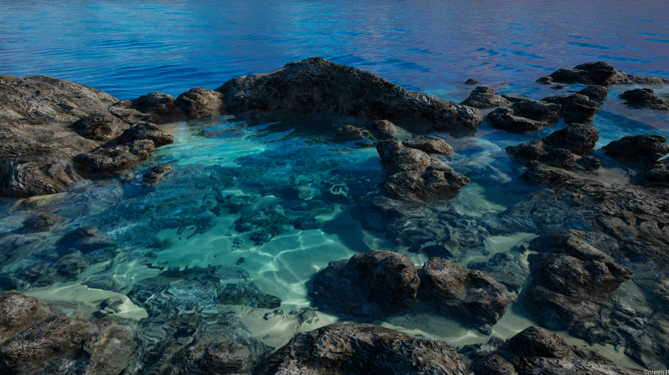
The Single Layer Water material shading model is a material that provides a cost-effective translucency method using a single depth layer. It is a physically-based shading model that supports proper light scattering, absorption, reflection and refraction, and shadowing on water surfaces.
Single Layer Water's Implementation
The Single Layer Water shading model uses a custom render pass to achieve its transparent result, and it can do so while using a Blend Mode that is either Opaque or Masked . The translucency of the material runs after the base pass and deferred lighting, but before regular translucency rendering, post-processing, and everything else that comes in the rendering pipeline.
Single Layer Water shading is a homogeneous volume of a participating medium that uses scattering and Schlick Phase Functions with contributions from the Opaque or Masked water surface. The transparency of the surface is implicit in the volume shading model. Refraction is also handled by the volume function, which reads the depth and color below the surface before distorting the samples.
In the Material Editor, the Single Layer Water Material node has four inputs: Scattering Coefficients , Absorption Coefficients , PhaseG , and Color Scale Behind Water . These inputs define the look of the water. How translucent the water is is handled by the main material node's Opacity input, whereby it controls the ratio between the volume's bi-directional scattering distribution function (BSDF) and the surface's bi-directional reflectance distribution function (BRDF).
You can use RenderDoc to perform a frame capture that allows you to see where the Single Layer Water pass happens in the GPU capture. When the Single Layer Water pass happens, the BasePass has already been rendered and lit. The fully lit scene and depth are used as input to the Single Layer Water pass, and reading the buffers is how refraction and translucency is achieved for an Opaque or Masked material.

Prior to the first item in the list, you can use an optional step to downsample the scene color and depth buffer for the refraction reads. This can speed up rendering but gives a slightly blurry (or low resolution) appearance to objects rendered below the water's surface.
-
All objects with SingleLayerWater are rendered into the GBuffer (including depth) using the user-defined material.
-
A compute shader is run to tile-classify all of SingleLayerWater based on the MaterialID in the GBuffer.
-
Generated screen tiles are used for an indirect draw screen space reflections (SSR) pass, which is run and output to a separate buffer.
-
Generated screen tiles are used again to run an indirect draw full screen pass to composite reflection captures, sky, and newly computed screen space reflections on top of the water's surface.
Single Layer Water Low-end Systems and Mobile Support
In situations where lower-end systems and platforms, such as mobile and low-end desktop, an alternative render path is used that skips some of the features of Single Layer Water in favor of performance. The simplest alternative reverts the material to a simple translucent material with no volume integration, or screen space reflections.
Using Single Layer Water Material Output
When creating a material, set the following in the Details panel:

-
Blend Mode: Opaque or Masked
-
Shading Model: SingleLayerWater
Add a Single Layer Water Material output node to the Material Graph. This output expression defines the look of water for light scattering and absorption, anisotropic or isotropic directionality (PhaseG), and color contribution on surfaces that are below the water surface (for example, caustics and shadows).

Scattering Coefficients
The Scattering Coefficients input represents the rate at which light scatters on particles within a medium — in this case, water. The amount of light scattering that takes place within the medium determines how light and color look for objects within the medium. When there is a low amount of scattering through the medium, such as glass or a bottle of water, the medium appears clear. Light will not scatter as much through the medium, allowing light to pass through more readily. In cases where there is a high amount of scattering, light scatters more preventing it from passing through the medium. This causes the medium to appear thicker, or more opaque, like orange juice or milk.
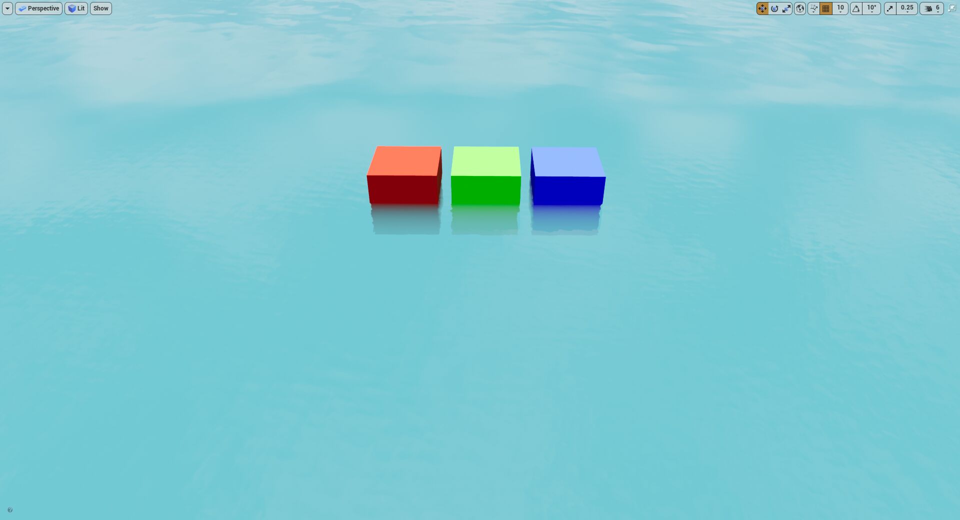
The amount of scattering affects how light travels through the medium, and that directly impacts the way things look when an object is within its volume. For example, if there are three cubes (red, green, and blue) that are within the medium, and the material is set to only scatter blue light, notice how the scattered blue light affects the color of all the cubes (left) compared to a material where no scattering is happening (right).
|
|
|
|---|---|
|
Blue light scattering in the medium |
No light scattering happening |
Applying this concept to the default Water Body material, notice how it looks when some amount of scattering is applied, compared to no scattering at all. When there is no scattering, light doesn't bounce or get dispersed in the same way, so the cubes are visible farther down than they are when light is scattered.
Using a higher amount of scattering gives a thicker appearance and consistency to the water. Light scatters much more through the medium, making it more difficult to see objects the deeper they travel. The example below demonstrates the effect of having different amounts of light scattering, from a lower amount to a very high amount, and then to the point where it is impossible to see any part of the cubes below the surface.
Absorption Coefficients
The Absorption Coefficient input defines how easily light penetrates the volume of water (or participating medium). Each color channel (RGB), or wavelength of light, penetrates water differently, some better than others. When light is absorbed by the medium it's traveling through, it goes extinct, meaning it loses its color. The farther an object travels into a medium with a high absorption coefficient, the more likely its color will dissipate.
Absorption coefficients control what colors of light are likely to be absorbed more quickly in a medium. Small coefficients allow for light to transmit easily through the medium, giving it a more transparent appearance. Large coefficients attenuate light more quickly as it passes through the medium, giving it a less transparent appearance.
The example below shows three cubes (red, green, and blue) moving farther into the medium. When using a moderate absorption coefficient for these primary colors (Red =0.0033, Green = 0.0016,Blue = 0.0011), the results show how each color dissipates as they move deeper into the medium. First red goes extinct, then green, and finally blue.
Using the same values and setup as above with the default water material, the three primary-colored cubes each lose their coloring as they submerge and travel deeper into the water. Their colors become extinct in the same order.
When using the default water material, the absorption coefficient values are reversed. Larger values cause colors to go extinct quicker than lower values. The distance light travels through the volume is expressed in reciprocal meters, meaning that it is expressed by dividing 1 by the absorption distance in your material.
The distance setup used looks like this:

PhaseG Function
The PhaseG parameter controls the overall forward or backward direction that light scatters in water. More specifically, this parameter controls the anisotropic directionality of scattered light relative to the direction of the sun.
PhaseG takes in values that are positive or negative, where positive values increase how much light is scattered toward (forward) the sun and negative values increase how much light is scattered away (backward) from the sun. This can have the effect of water looking brighter or darker depending on the current view and where the sun is in the sky.
|
|
|
|---|---|
|
PhaseG: -0.75 |
PhaseG: 0.5 |
When the PhaseG value is 0, its light directionality is isotropic, meaning that light scatters the same in all directions.
The phase function gives water a more defined shape, especially when there are waves present. This is because after refraction occurs, the view ray changes directions, adding variation to the amount of light being scattered through the water.
Color Scale Behind Water
The Color Scale Behind Water input multiplies the luminance of the surfaces below the water. This type of effect is used within your material to drive how bright or dark caustics or shadows can be.
The comparison below demonstrates how visible caustics can be on surfaces below the water.
This is simply a visual effect of the material, which is visible above the water material. Moving below the surface of the water does not change the brightness of surfaces behind the water nor does it actually project caustics or shadowing on these surfaces.
Water Opacity
When using a material setup to use Single Layer Water, the Opacity input on the main material node controls the visible parameter of water. The amount of opacity controls how much light is allowed into the volume and scattered. It also controls how far you're able to see through the volume. Larger opacity values are more opaque, not allowing light to penetrate the surface. Lower values allow all light to pass through the surface so you can see much farther into the water.
Having low, or no, opacity also allows for the other properties of the Single Layer Water Material output expression to work unencumbered. In the table below, having no, some, or maximum values for the opacity of the water material allows all, some, or no light to pass through the volume. Having a completely opaque material (Opacity = 1) has a dark appearance as no light is allowed through the surface to scatter through the water.
|
|
|
|
|---|---|---|
|
Water Opacity: 0 |
Water Opacity: 0.5 |
Water Opacity: 1 |


