UDN
Search public documentation:
ParticleSystems
日本語訳
한국어
Interested in the Unreal Engine?
Visit the Unreal Technology site.
Looking for jobs and company info?
Check out the Epic games site.
Questions about support via UDN?
Contact the UDN Staff
한국어
Interested in the Unreal Engine?
Visit the Unreal Technology site.
Looking for jobs and company info?
Check out the Epic games site.
Questions about support via UDN?
Contact the UDN Staff
Particle Systems
Document Summary: A comprehensive guide to Emitters using the new Particle System Editor (available in the UDN build). Document Changelog: Last updated by Chris Linder (DemiurgeStudios?), to update for UDNBuild 2226. Original authors were Albert Reed, Chris Linder, and Tom Lin (DemiurgeStudios?).Unsupported Disclaimer
The code described in this document is provided to you as a service of UDN or other licensees. It is not supported by Epic.Introduction
Particle systems are tools for creating various effects which cannot be creating using static geometry or animations. These effects are achieved by having several instances of the same thing, usually sprites, move and change in a pattern. Using this simple concept artists can create effects as diverse as waterfalls, flames and lightening.Quick-Start
Creating the Particle System
Begin with a new map and subtract out a 1024x1024x1024 cube from the world (If you need more help with this check out the UnrealEdInterface document) If you prefer, you may edit an existing level. Add a few lights to the empty cube and do a Build->Build All. Your level should look something like this: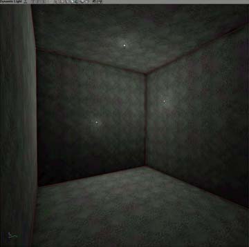 With the room setup, open up the actor browser and select Emitter.
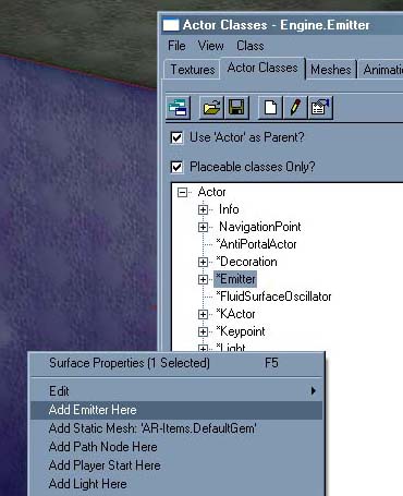 Right-click on the far wall and select Add Emitter Here.
With your emitter created we are now ready to start editing it. Before we do however, make sure you have Realtime Preview turned on by clicking the joystick at the top of the viewport like this:
Right-click on the far wall and select Add Emitter Here.
With your emitter created we are now ready to start editing it. Before we do however, make sure you have Realtime Preview turned on by clicking the joystick at the top of the viewport like this:
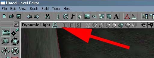 With that selection you'll be able to see the changes you make to your emitters update in realtime. Before moving on, drag the emitter to the middle of the room so there will be plenty of space when it begins emitting particles.
Editing the Particle System
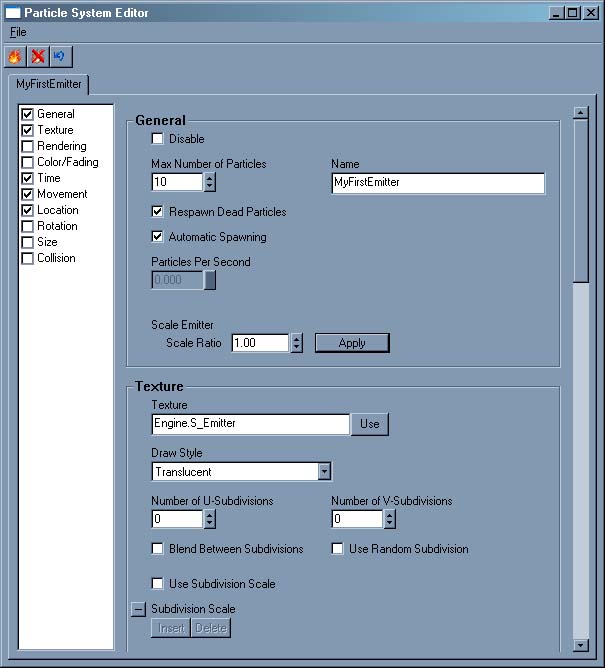
With the emitter selected pull down Particle Editor from the Tools menu in UnrealEd. A window like this will appear: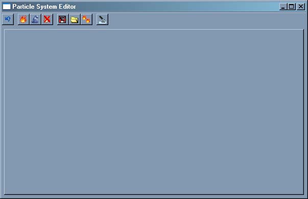 .
From this tool you will be doing all of your particle editing.
.
From this tool you will be doing all of your particle editing.
Adding a Sprite Emitter
The introduction of this manual explains that particle systems can be made up of Sprite Emitters. The first thing to do is to add a sprite emitter to your particle system. To do this click the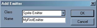 .
This will create a new Sprite Emitter called "MyFirstEmitter". After you click okay. The Particle System Editor will now look like this:
.
This will create a new Sprite Emitter called "MyFirstEmitter". After you click okay. The Particle System Editor will now look like this:
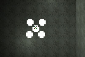
 If everything worked correctly, you'll notice your particle system has begun spitting out some ugly particles and will look like this:
 .
.
Making Them Move
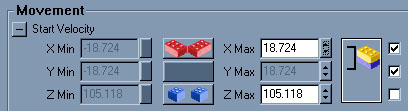
Right now the particle system doesn't do much at all. The first step in making it a bit more interesting is to get the particle to move rather than piling up in one place. To do this select the Movement category from the left-hand column. The large scrolling area on the right will zip down to the Movement heading. Fill in the values under Start Velocity to look like this and things will start to happen.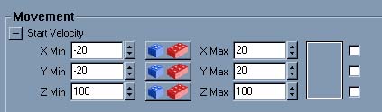
The Start Velocity settings, like most of the settings in the particle system editor change things in real time. You can type numbers in or you can click and drag the buttons next to the fields to change values and watch the system change as you drag. You can also "link" values together so you don't have to change each one individually.
Picking a Texture
Another major change you can make to a particle system is to change the texture it is using for the sprites. From the texture browser, select a texture and then under the Texture category click the Use button in the Texture field.Play around
Take some time to play around with all the properties available to you. They may not all make sense the first time around but most do what they say. If at anytime you want further explanation visit the reference section of this document. Acceleration, Max Number Of Particles, Lifetime, Fading, and Start Location are all good places to start.Particle Editor Interface
Adding an Emitter
To add an emitter to a particle system click the
Give your particle system a name and select the type you would like and click Ok.
Editing Emitters
Categories
The left column contains a list of categories which organize the various properties of a given emitter. Clicking on the categories will scroll to that set of variables. Checking and unchecking the boxes will show and hide those categories.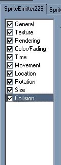
Controls
There are several types of controls that are used in the particle system editor. Almost all of the controls have fields where you can values and watch the particle system change. Some properties will force the system to re-start others will update smoothly in realtime. All of the numeric fields have "Scroll Buttons"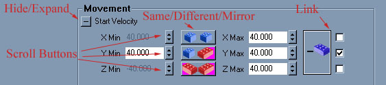 Some controls have mins and maxes. In addition to being able to set the individual components of the vector with the scroll buttons, you can click the Different/Same/Mirror button to alter the min and max of a variable in sync.
 - The blue and red Lego signify that you can edit min and max independent of each other.
- The two blue Legos signify that the values in min and max will be kept the same.
- The two red Legos signify that the min and max values will be mirrored. For example, setting the max to 40.0 will automatically set the Min to -40.0.
Deleting an Emitter
Clicking the Delete Emitter buttonRefreshing
Many particle systems aren't designed to be going constantly. For example, a muzzle flash or breaking glass need to be restarted in order to preview them properly. Clicking the Refresh ButtonExporting
If you need to spawn a particle system dynamically in-game you'll need to make a script out of it. You might also want to make a script so that your particle system is availible in the actor browser. To create a script click the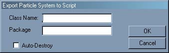 Fill in the package and name of the actor you want to create and click Ok to export the script. Checking Auto Destroy creates an actor that will delete itself when it no longer has particles. You will need to recompile the package the script was exported to in order for it to work or show up in the editor.
Duplicate Emitter
Clicking theSave/Load Emitter
Individual emitters can be saved to ".emt" files for later use by clicking theGetting Help
You can also use the context-help toolParameter Reference
The referance section of this document borrows heavily from Lode Vandevenne's original emitter tutorial which is masterful piece of work from dark and troubled times.General
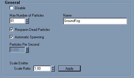
Disable
If Disable is checked, the particle emitter will not work. You can for example use it if you want to remember the settings of a p particle emitter, but you currently don't want it to work in the map.Max Number of Particles
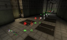
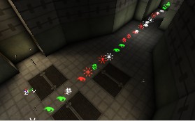
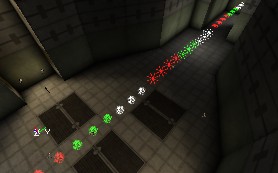
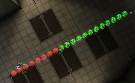
The Max Number of Particles setting sets the maximum number of particles that may be on screen for this Particle Emitter. If the maximum number is reached, the oldest particle gets killed, so a new one can get spawned. If you set it to 0, the editor crashes. For example, if you set this number to 4, there will be 4 particles on screen once the warmuptime is over. On the screenshot, the particles are moving to the left, and the most left one gets destroyed while a new one appears on the right: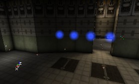
This setting is quite important, especially if you want to reduce the amount of particles on screen to get more performance.
Name
This parameter simply gives the particle system a name. Next time you load the editor, the new Name will appear on the tab.Respawn Dead Particles
Unchecking this box will cause dead particles not to respawn. If you are making an explosion or other tempoary effect, uncheck this box.Automatic Spawning
Automatic Spawning causes the number of particles to remain equal to Max Number of Particles regardless of other particle system properties. For example, with this box checked and Max Particles set to 10 once the system warms up there will always be exactly 10 particles regardless of the Lifetime of the system. With Automatic Spawning checked you cannot directly control how many Particles Per Second are spawned.Particles Per Second
With Automatic Spawning unchecked, you can now control the rate at which your particles are released. Keep in mind that no matter what you can not cause there to be more particles than what Max Particles is set to.Scale Emitter
This tool adjusts several properties throughout the editor to make your emitter larger or smaller. Pick a value and click the apply button to scale the emitter.Texture

Texture Picker
Select a texture from the texture browser and click the Use button to use that texture on your emitter.Draw Style
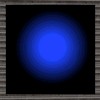
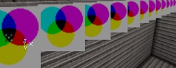
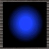
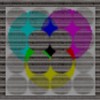
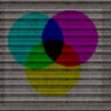
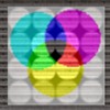
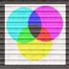
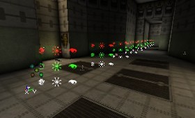
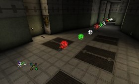
Using the Draw Style property you can change the way the texture is drawn in the map. The Draw Style for Particles is somewhat the same as the Draw Style you find under Display of normal actors, but has some added options, and some other removed. For the example screenshots, the blue texture is one without alphachannel, and the second one is a texture with different colors and an alphachannel that has 16 dark dots, like this: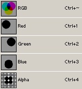 Regular makes the texture opaque, so it's a non-transparent square.
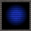

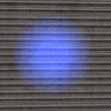
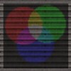
 Alpha Blend makes the darker parts of the A-channel of the RGBA texture more transparent than the bright parts. Black becomes 100% transparent (invisible) and white becomes 100% opaque. Grey becomes semi-transparent. This effect is not good visible on very bright textures.
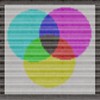
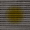
 Modulated makes the texture some sort of inverse translucent: it makes the brightest colors of the texture more transparent than the darkest colors, so black becomes opaque, white becomes 100% transparent (invisible). Grey, red, blue, etc... become semi-transparent.
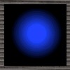
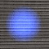
 Translucent makes the darkest colors of the texture more transparent than the brightest colors, so white become opaque, while black become 100% transparent (invisible). Grey, red, blue, etc... become semi-transparent.
 AlphaModulate makes the actual RGB texture brighter on places where the alphachannel is darker. It looks somewhat the opposite of Alpha Blend. This effect isn't good to see on very bright textures.
 Darken makes the colors of the texture negative and translucent.
 Brighten makes the texture to brighten the background, so the texture becomes translucent and brighter than it's original version.
 As you can see, the alphachannel of an RGBA8 texture is only used for the Draw Styles Alpha Blend and Alpha Modulate.
Subdivisions
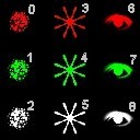
You can divide one texture into different subdivisions. You can make the particles randomly pick one of the textures, or make one particle change from one subdivision to another during it's Lifetime. You have to make a texture that can be used for this yourself: divide into a * b equal rectangles, and give every rectangle it's own picture. For example, this is a texture that can be divided into 3 * 3 = 9 Subdivisions: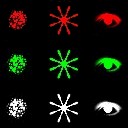 To set the Subdivisions, use U-Subdivisions and V-Subdivisions for the horizontal and vertical Subdivisions.
Setting these settings to 0 or 1 does exactly the same: it divides the texture into 1 Subdivision, meaning there are no Subdivisions at all (the Subdivision is the texture itself), so the particles will look like this:
To set the Subdivisions, use U-Subdivisions and V-Subdivisions for the horizontal and vertical Subdivisions.
Setting these settings to 0 or 1 does exactly the same: it divides the texture into 1 Subdivision, meaning there are no Subdivisions at all (the Subdivision is the texture itself), so the particles will look like this:
 If you set both U-Subdivisions and V-Subdivisions to 3, it looks like this:
 If you set them to 2 or 4, some pictures of this texture will be cut into half, because it has 3 * 3 Subdivisions and isn't made for other values.
 If you set respectively U-Subdivisions=1 and V-Subdivisions=3 or U-Subdivisions=3 and V-Subdivisions=1, it'll look like this:
 If you check the Use Random Subdivision box the Emitter will give each particle a random Subdivision at the beginning, and the particle keeps this Subdivision as long as it lives.
 If leave Use Random Subdivision un-checked, the particles will change during their Lifetime. For example if you'd have 2 * 2 Subdivisions, then first they'll have the upper left Subdivision, then the bottom left, then the upper right and finally the bottom right. The time it takes to change from one Subdivision to another, depends on their Lifetime, more about this further in the section Time. On the screenshot, there are 9 Subdivisions.
 If you check Blend Between Subdivisions (and Use Random Subdivision is not checked), the particles will Fade from one Subdivision to another:
 Normally, the particles go through the different Subdivisions this way, that they will have all the Subdivision one for the same amount of time. The time is divided in equal parts for each Subdivision. If you don't want this, you can use the Subdivision Scale feature. To do this, first check the Use Subdivision Scale box. Next, click the Insert button under Subdivision Scale that so there are 3 Subdivision Scales (then 4 of the 9 Subdivisions will be used). If you want the 9 Subdivisions to be used, you have to make 8 Subdivision Scales. If you make less than 8 Subdivision Scales, the last Subdivisions will never appear. There's also nothing wrong with making too many Subdivision Scales, then the last ones will just be ignored.
The Subdivision Scale is relative to the Lifetime of the particles (see the section Time for this), so a Subdivision Scale of 1.000000 takes as long as the Lifeime of the particles. Each Subdivision Scale represents a certain point in the Lifetime of the particle. For example if the Lifetime is 4 seconds, a Subdivision Scale of 0.25 is the end of the first second of the Lifetime. A successive Subdivision Scale should always be larger than the previous one, otherwise you're going back in time and it will be ignored. For example if you make Subdivision [0] = 0.1, [1] = 0.3 and [2] = 0.6, and LifeTimeRange is 4 seconds, the particle will have Subdivision 1 for 0.4 seconds, then Subdivision 2 for 0.8 seconds, Subdivision 3 for 1.2 seconds and Subdivision 4 for the remaining 1.6 seconds. On the screenshot, the particles move from left to right.
Normally, the particles go through the different Subdivisions this way, that they will have all the Subdivision one for the same amount of time. The time is divided in equal parts for each Subdivision. If you don't want this, you can use the Subdivision Scale feature. To do this, first check the Use Subdivision Scale box. Next, click the Insert button under Subdivision Scale that so there are 3 Subdivision Scales (then 4 of the 9 Subdivisions will be used). If you want the 9 Subdivisions to be used, you have to make 8 Subdivision Scales. If you make less than 8 Subdivision Scales, the last Subdivisions will never appear. There's also nothing wrong with making too many Subdivision Scales, then the last ones will just be ignored.
The Subdivision Scale is relative to the Lifetime of the particles (see the section Time for this), so a Subdivision Scale of 1.000000 takes as long as the Lifeime of the particles. Each Subdivision Scale represents a certain point in the Lifetime of the particle. For example if the Lifetime is 4 seconds, a Subdivision Scale of 0.25 is the end of the first second of the Lifetime. A successive Subdivision Scale should always be larger than the previous one, otherwise you're going back in time and it will be ignored. For example if you make Subdivision [0] = 0.1, [1] = 0.3 and [2] = 0.6, and LifeTimeRange is 4 seconds, the particle will have Subdivision 1 for 0.4 seconds, then Subdivision 2 for 0.8 seconds, Subdivision 3 for 1.2 seconds and Subdivision 4 for the remaining 1.6 seconds. On the screenshot, the particles move from left to right.
 If you make Subdivision Scale [0] = 0.4 and [1] = 1, only two of the Subdivisions will be used. Then it doesn't matter anymore what value you entered in [2].
 To get this effect at it's best, you have to use the correct LifeTimeRange and also make sure the Number of Particles value is high enough. Read sections General and Time for this.
Use the Subdivision End and Subdivision Start values if you want only a few Subdivisions of the texture to be used. Subdivision 0 is the Subdivision in the upper left corner of the texture, Subdivision 1 the one below that, and the last one is in the lower right corner of the texture. This picture shows the numbering:
To get this effect at it's best, you have to use the correct LifeTimeRange and also make sure the Number of Particles value is high enough. Read sections General and Time for this.
Use the Subdivision End and Subdivision Start values if you want only a few Subdivisions of the texture to be used. Subdivision 0 is the Subdivision in the upper left corner of the texture, Subdivision 1 the one below that, and the last one is in the lower right corner of the texture. This picture shows the numbering:
Custom Texture Set
This option is only shown when the emitter is a mesh emitter. This is different set of textures to use instead of the standard texture for the selected mesh. See Mesh for more details on mesh emitters.Rendering
Disable Fogging
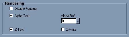
If chcked, the fogging on the particles will be disabled, so you can see them through the distance fog.Alpha Test/Alpha Ref
When checked, the video hardware will not write pixels that already has accumlated an alpha value of Alpha Ref.Z-Test
The the default and normal behavior for emitters is with this box checked. Unchecking this box makes the emitter draw on top almost everything. This may not draw on top of other emitters with z-test unchecked or other alpha'ed objects.Z-Write
This causes the particles to write to the Z-buffer. ("In a graphics card, this section of video memory keeps track of which onscreen elements can be viewed and which are hidden behind other objects." - CNET Glossary)Color/Fading
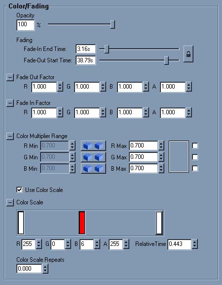
Opacity
This utility tool will adjust the translucency of the entire emitter. It changes several properties in the Color/Fading category.Fading
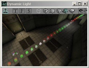
With this, you can make the particles fade in or fade out, for example when they fade in they are invisible at the beginning and become more and more visible. You can also make only a few of the colorchannels fade, so for example the red and green parts of the texture will be invisible while the blue parts are always visible. To cause your particle emitter to fade in, drag the Fade-In End Time slider away from the left side. On the screenshot, the particles have a Lifetime of 5.0 and a Fade In End Time of 5.0, so they are 100% visible at the moment they die: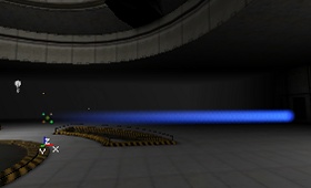 Fade-Out Start Time works the same as Fade-In End Time. If this is 0 (Slider all the way to the left) the particles will will already start fading when they're born and be completely Faded out at the moment they die. On the screenshot, Fade-Out Start Time is 1.
Fade Out/In Factor
You can use Fade In Factor and Fade Out Factor to fade individual color channels. If the values are 1, the particles fade normally. If you make for example R = 0, the red channel will get changed 0%, so while the other colors are invisible (this is at the start of a fade in, or the end of a fade out), the red will still be visible (left part of the first screen). Or when G = 0, the green will still be visible (right part of the first screen). If R and G are 0, both will be visible, it looks somewhat yellowish here (left part of the second screen). If R, G and B are 5, the whole texture will get super-invisible so it fades out much faster (right part of the second screen). If R, G and B would all be 0, the texture wouldn't get invisible at all.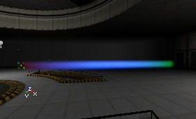
Color Multiplier Range
The Color Multiplier Range is a multiplier that is applied to each particle individually at the start of its lifetime. This can be used in two main ways; to give the particles random variation in color, and to adjust the color of the emitter without having to change the texture or the color scale. To give the particles a slightly random color set the min and max of a field to different values; the wider the range the more the variation in color. To adjust the color of the emitter just change the value of R, G, or B to make the emitter less Red, Green or Blue.Use Color Scale
This turns on the use of color scale and color scale repeats (see below)Color Scale
This is another scale that can be applied to the particles. A scale changes something of the particle during its lifetime, in this case the color. To use a Color Scale, first set "Use Color Scale" to True, and then add a new color bar. To add a new a new color bar double click somewhere in the color scale box. This will bring up a color picker window where you can pick a color and click OK. This will show the color you choose on a vertical bar where you double clicked.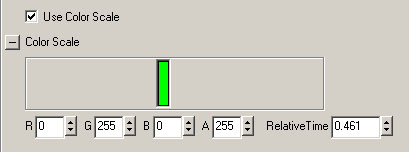 You can change this color at any time by double clicking on the color to bring up the color picker window or by single clicking on the color and manually adjusting the R, G, B, and A values. The alpha values (which only are only relevant for alpha blend mode) must be changed manually in this way because the color picker does not support alpha. The color in the color bar is combined with the color of the texture so if your texture is bluish and your color bar is white, the particle will still look bluish. If the color bar is cyan on the other hand, the particle will look more cyan but not as cyan as the color bar. White textures generally work best with color scale because they take the color of the color bars best.
The position of the color bar represents the relative time of this color. This is the time in the life of the particle that the particle will be the color you have chosen. If the color bar is in the middle of the Color Scale the value will be somewhere around 0.5. If the lifetime of the particles is 4.0 seconds, about 2.0 seconds into the particle's life it will be the color you have chosen. The relative time can be changed by dragging the color bar or manually adjusting the relative time field below the Color Scale box.
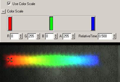
Color scale is most useful with two or more color bars. If you do not have a color bar at the far right of the Color Scale box, the color of the particles will pop back their normal color after the rightmost color bar. This is generally undesired. If you do not have a color bar at the far left of the Color Scale box, the system will behave as if there is a white color bar there. This is an example of 3 color bars used with a white texture. The middle color bar is selected so the field values correspond to that color bar.
You can change this color at any time by double clicking on the color to bring up the color picker window or by single clicking on the color and manually adjusting the R, G, B, and A values. The alpha values (which only are only relevant for alpha blend mode) must be changed manually in this way because the color picker does not support alpha. The color in the color bar is combined with the color of the texture so if your texture is bluish and your color bar is white, the particle will still look bluish. If the color bar is cyan on the other hand, the particle will look more cyan but not as cyan as the color bar. White textures generally work best with color scale because they take the color of the color bars best.
The position of the color bar represents the relative time of this color. This is the time in the life of the particle that the particle will be the color you have chosen. If the color bar is in the middle of the Color Scale the value will be somewhere around 0.5. If the lifetime of the particles is 4.0 seconds, about 2.0 seconds into the particle's life it will be the color you have chosen. The relative time can be changed by dragging the color bar or manually adjusting the relative time field below the Color Scale box.
Color scale is most useful with two or more color bars. If you do not have a color bar at the far right of the Color Scale box, the color of the particles will pop back their normal color after the rightmost color bar. This is generally undesired. If you do not have a color bar at the far left of the Color Scale box, the system will behave as if there is a white color bar there. This is an example of 3 color bars used with a white texture. The middle color bar is selected so the field values correspond to that color bar.
Color Scale Repeats
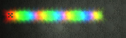
With "Color Scale Repeats", the Color Scale process can be repeated an arbitrary number of times. The default is 0 which means that the color scale with work once, but not repeat any times. With the value set to 1.0, there will be two scales, once for the normal color scale and one repeat. This is the same color scale as above but with "Color Scale Repeats" set to 1.0.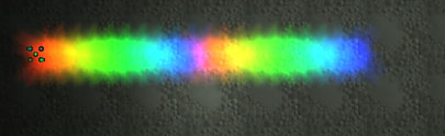 This is an image with color scale repeats set to 2.5. Note how the color ends on green, which is in the middle of the color scale.
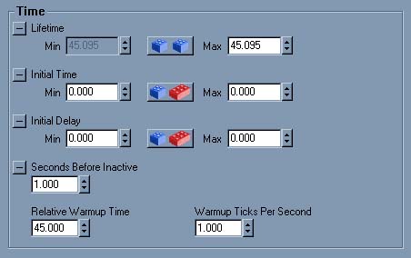
Time
 #Lifetime
Lifetime
The Lifetime is the number of seconds the particle will live. After this time, it gets destroyed and might respawn.Initial Time
The _Initial Time_ lets the particles be several seconds old already when they get spawned. If Lifetime is 4 and _Initial Time_ is 3, the particle will already be 3 seconds old when spawned and live for only one second. This setting can be interesting when you use scales: the Subdivision Scale, Color Scale and SizeScale will also be calculated as if they're 3 seconds old already.Initial Delay
The Initial Delay is the time it takes before the emitter starts its job. For example, if you enter an Initial Delay of 5, when you start the map or click [[#Refreshing][refresh], it'll do nothing for 5 seconds before it starts emitting. For all the settings you can use a Min and Max value. If you make them the same, that exact value will be used. If you make Min smaller than Max, every particle will get it's own random LifeTimeRange or InitialTimeRange when it gets spawned, and this random value is something between Min and Max. If you use a random LifeTime, the particles will look like the screenshot at constant speed: there appear holes because some of the particles die already while others are still continuing their way.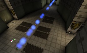
Seconds Before Inactive
When this value is 0.000000, the movements of the particles are always calculated by the computer, even if they're out of view. If you enter a value in here, the computer will stop calculating the movements of the particles after the Emitter actor is out of view for this many seconds. This way you gain performance. So when you look away from the Emitter, the particles will freeze, and only come back to life when you look at them again. So when Seconds Before Inactive = 0.010000 and you see this: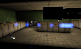 and then rotate the camera 180�, wait an hour and then look again at the Emitter, you'll still see exactly the same image (where the warmup is not finished yet). When you can't see the Emitter actor, but you should be able to see some particles, you will not see these particles! Only when you can see the Emitter itself, you'll be able to see it's particles. If you don't want this, set _Seconds Before Inactive to 0.000000.
Relative Warmup Time/Warmup Ticks Per Second
You can make the engine precalculate the Emitter, so when you start the map it's as if the Particle Emitter has been there already for a few seconds and you will not see the warmup effect. The warmup is the time where not yet all the particles are spawned. With the setting Relative Warmup Time you can set how many seconds have to be precalculated, relative to the Lifetime of the particles. This means if you set it to 1, there are exactly as much precalculated seconds as the first particles will live. But before this works you also have to set the WarmupTicksPerSecond: this is how many ticks each second of the RelativeWarmupTime has. The higher the Warmup Ticks Per Second, the more there will be precalculated. In short, the longer the Relative Warmup Time of a certain Particle Emitter takes, the higher you have to make the Warmup Ticks Per Second setting (and set Relative Warmup Time to 1) if you want there to be no visible warmup.Movement
Start Velocity
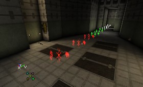
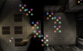
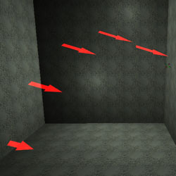
Use Start Velocity to give the particles a constant speed. The X, Y and Z values will adjust how fast the particles travel in that direction. If Min and Max are the same, you get what you would expect: the particle moves with the speed you entered to the direction you used. If Min < Max, the particle will move with a random, constant speed that is something between the Min and Max value. For example, if you set X-Min equal to X-Max and Y-Min equal to Y-Max and Z-Min equal to Z-Man (and make sure there is no acceleration), all the particles will move towards the same direction: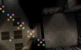 But if you set X-Min to -500 and X-Max to +500 (and keep the Y values), the particles will move with a random direction:
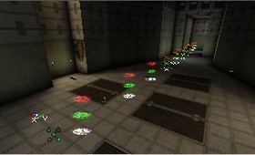
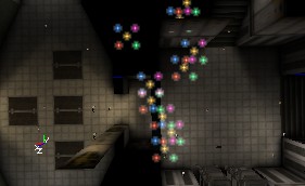
 If you'd have made X-Min = -150 and X-Max = +150, there'd be less difference in the directions:
Acceleration
To make the particles moving, you can give them Velocity and/or Acceleration. The Acceleration makes them move faster and faster, and is very easy to set up: open the properties of the Emitter and in there open the properties of the Sprite Emitter. In there, expand Acceleration. There you can enter the amount of Acceleration you want along the X, Y and Z axis. You can enter negative values too. If you assume that the upper part of the Top View is the North, here's what the settings do: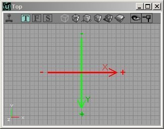 If X > 0, the particle will go to the East
If X < 0, it'll go to the West
If Y > 0, it'll go to the South
If Y < 0, it'll go to the North
If Z > 0, it'll go to the ceiling or sky
If Z < 0, it'll go to the ground
The total acceleration is the sum of these 3 components, so if X = 425, Y = -950 and Z = -950, the particles will go to the North-East and down, and will go to the North with more acceleration than to the East. However, if you rotated the Emitter actor with the Rotation tool, this won't be correct anymore, the CoordinateSystem will be rotated then. The X-axis will then be the direction of the arrow if you set bDirectional to True in advanced. Once you gave it some acceleration, you'll see the particles move.
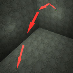
While Acceleration makes the particle move faster every second, the Start Velocity is a constant speed. If no Acceleration is used, but there is a Velocity, the particle will move with the same speed as long as it lives. If you use Velocity AND Acceleration the total speed of the particle will be the sum of the constant Velocity and the variable speed caused by the Acceleration. If there is a Velocity and a Acceleration along the same axis, but they have opposite signs, the particle will first move in one direction, but at a certain point the absolute value of the speed caused but the Acceleration will be larger than the absolute value of the Velocity, so the particles will move back to the direction they came from. If you use a Velocity and an Acceleration, both along a different axis, the particles will make a parabola. A parabola is the realistic trajectory for example a bullet or an object you throw follow. For example if Acceleration has Z = -950, and Start Velocity has X-Min = 500 X-Max = 500, it'll look like this:
If X > 0, the particle will go to the East
If X < 0, it'll go to the West
If Y > 0, it'll go to the South
If Y < 0, it'll go to the North
If Z > 0, it'll go to the ceiling or sky
If Z < 0, it'll go to the ground
The total acceleration is the sum of these 3 components, so if X = 425, Y = -950 and Z = -950, the particles will go to the North-East and down, and will go to the North with more acceleration than to the East. However, if you rotated the Emitter actor with the Rotation tool, this won't be correct anymore, the CoordinateSystem will be rotated then. The X-axis will then be the direction of the arrow if you set bDirectional to True in advanced. Once you gave it some acceleration, you'll see the particles move.
While Acceleration makes the particle move faster every second, the Start Velocity is a constant speed. If no Acceleration is used, but there is a Velocity, the particle will move with the same speed as long as it lives. If you use Velocity AND Acceleration the total speed of the particle will be the sum of the constant Velocity and the variable speed caused by the Acceleration. If there is a Velocity and a Acceleration along the same axis, but they have opposite signs, the particle will first move in one direction, but at a certain point the absolute value of the speed caused but the Acceleration will be larger than the absolute value of the Velocity, so the particles will move back to the direction they came from. If you use a Velocity and an Acceleration, both along a different axis, the particles will make a parabola. A parabola is the realistic trajectory for example a bullet or an object you throw follow. For example if Acceleration has Z = -950, and Start Velocity has X-Min = 500 X-Max = 500, it'll look like this:
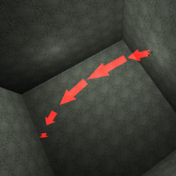
 If you now set also the X of Acceleration to -1000, it'll do the following:
Max Velocity
The sum of the velocity caused by the Acceleration and the Velocity is the Absolute Velocity, and you can set a Max Velocity value for every axis. If you use this, the Acceleration will keep speeding up the particle until the Max Velocity speed is reached. The particle will then have a constant speed. If you change the first parabola example to have Z value of Max Velocity to 600, the function will look like a parabola in the beginning, but once the absolute value of the speed along the Z axis is 600, the function will become a constant function (a line).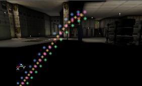
Velocity Loss
The Velocity Loss setting hinders the particle from moving along any axis you chose (if you set X = Y = Z it will slow down particles the same no matter which way they are moving). It works sort of like friction or air resistance. If it's larger than 100, the particles suddenly get shot away at very high speed. Again, you can use a Min and Max value if you want the Velocity Loss to be something random between the Min and Max value.Add Velocity From Other Emitter
Add Velocity From Other Emitter gives the particles the same Velocity as a random particle coming from another Particle Emitter inside the same Emitter actor. This setting works very similar to [[#AddLocationFromOtherEmitter][Add Location From Other Emitter] in Location.Add Velocity Multiplier
If Add Velocity From Other Emitter is not set to None then the particle's velocity will be multiplied by this value. For example, if you want the particles from this emitter to have twice the velocity of the particles from other emitter you could set all the values in this tool equal to 2.0.Get Velocity Direction From
With Get Velocity Direction From, you can choose in what direction the Velocity is used. None is the default and works as explained above. With Start Position And Owner, the particles will go in the direction determinated by the start position of the particle, and the Emitter Actor, and it moves away from the Emitter. Owner and Start Position does the same, but now the particle will move from it's startposition towards the Emitter Actor and when it reached that keep going further. This only works if it's startposition is not the Emitter itself, more about this is in Location. (coming soon)Coordinate System
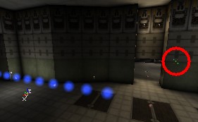
The CoordinateSystem determinates what the X, Y and Z values for the Location of the particles mean. If you set the CoordinateSystem to PTCS_Relative, the (X,Y,Z) = (0,0,0) position for the particles is the position of the Emitter actor in the editor, so the particles will get spawned there: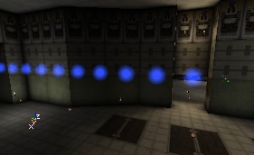 But if you set the CoordinateSystem to PTCS_Absolute, the CoordinateSystem of the world in the editor is used, and there the (0,0,0) Location is the exact center of the world (there the lines of the grid are painted a little darker than the others in the 2D views). So the particles will start in the center of the map (where the thicker gridlines in the 2D view cut each other), no matter where the Emitter actor is: note the emitter actor on the right of the screenshot:
 The default CoordinateSystem PTCS_Independent does the same as PTCS_Relative, but after they are spawned the particles become independent and use the absolute coordinatesystem. The difference between PTCS_Relative and PTCS_Independent becomes important when you use Moving Emitters.
All the three CoordinateSystems will rotate if you rotate the Emitter actor with the Rotation Tool. If you set in the properties of the Emitter actor in Advanced bDirectional to True, an arrow will be displayed in the editor to help you to rotate it better.
In the section Location is explained how you can make the particles spawn at another Location, again relative or absolute to the Emitter actor depending on the CoordinateSystem you use.
The default CoordinateSystem PTCS_Independent does the same as PTCS_Relative, but after they are spawned the particles become independent and use the absolute coordinatesystem. The difference between PTCS_Relative and PTCS_Independent becomes important when you use Moving Emitters.
All the three CoordinateSystems will rotate if you rotate the Emitter actor with the Rotation Tool. If you set in the properties of the Emitter actor in Advanced bDirectional to True, an arrow will be displayed in the editor to help you to rotate it better.
In the section Location is explained how you can make the particles spawn at another Location, again relative or absolute to the Emitter actor depending on the CoordinateSystem you use.
Min Squared Velocity
This controls the minimum velocity a particle may have before it becomes inactive. This is important if you use [[#CollisioN][Collision]: the particles will then get less velocity every time they bounce on the wall.Use Velocity Scale
 UseVelocityScale turns velocity scale on an off. Velocity scale is used to scale the velocity of the particle over time. Given that this is a component scale, velocity scale can be used to make the particles change direction over time and even reverse directions.
Velocity Scale
Velocity Scale allows you to scale the velocity of particles over the course of their lifetime. This can allow you to do things such as stop moving particles and then start them again. It can also allow you change the direction of particles by setting the X scale to 0.0 and the Y scale to 1.0 for one entry and then setting the X scale to 1.0 and the Y scale to 0.0 for another entry. Relative Velocity is a multiplier for the current velocity of the particle and Relative Time is the time at which that multiplier will be applied. As with all scales, the entries in Velocity Scale will be interpolated between.Velocity Scale Repeats
Velocity Scale Repeats is the number of times the Velocity Scale will be additional repeated. Setting this to 0 will cause the velocity scale to happen just once. Setting this to 1 will cause the velocity scale to happen twice.Location
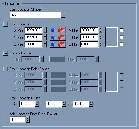
Start Location Shape
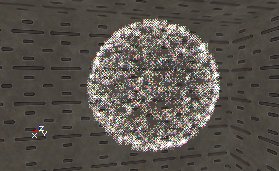
This will determine the overall shape that particle spawn in. Selecting Box uses the variables in Start Location to spawn all of the particles in the specified _ Box_. For example if you set X, Y and Z(Min) to -150 and X, Y and Z(Max) to +150, all the particles will start inside a 300*300*300 box. Selecting Sphere makes it possible spawn the particles inside of a sphere with a radius equal to the values inside of Sphere Radius.
 Polor is rather complicated, but uses the X, Y, and Z varibles in Start Location Polar Range as theta, phi, and r repsectively in the standard polar equation. Basically, this makes a hollowed partial-sphere with radius r. It will sweep longitudally theta degrees and latitdually phi degrees.
Start Location Offset
The settings in Start Location Shape work in combination with Location Offset, so the final Start Location is the sum of those. This makes is possible for spawning area of particles to not be centered over the emitter.Add Location From Other Emitter
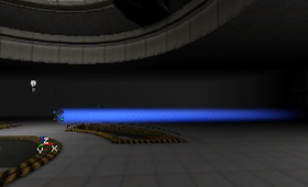
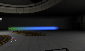
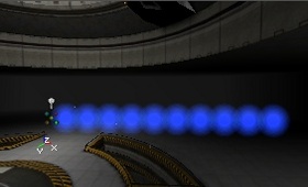
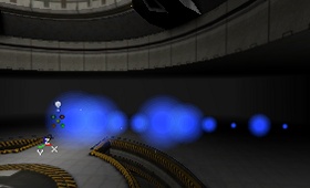
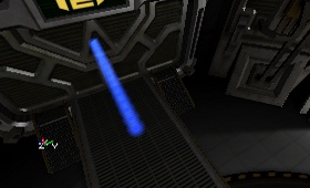
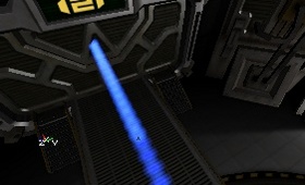
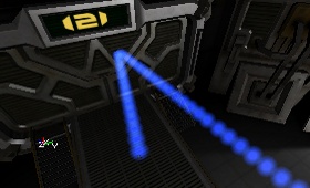
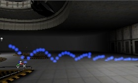
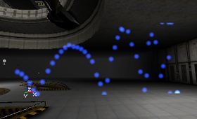
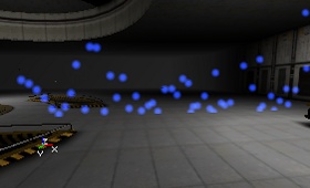
In Add Location From Other Emitter you can select another Particle Emitter that is inside the same Emitter actor. If you set it to something other than None, the particles will not be spawned where they normally should spawn, but at the location of one of the particles of the selected particle emitter. They will not keep following that particle, they only get spawned there and get independent after that. You can for example make a trace of particles behind another moving particle. This is done in the DEMO-Particles example map: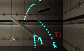 The blue sprites never move, but when they die they respawn at one of the bouncing balls, so together all the blue sprites form the shape of the traces the balls follow.
Mesh Spawning
 Mesh Spawning uses the vertices of a static mesh to calculate the spawn location and optionally the velocity and the color of the particles in this emitter. The static mesh does not have to exist in the world nor do the faces of the static mesh matter. This means that you can make arbitrary shapes for static meshes in a modeling program. You can also use existing static meshes in the world and attach effects to them to produce results like a bush on fire.
Mesh Spawning Type
| Mesh Spawning Type | Description |
|---|---|
| Do Not Use Mesh Spawning | Off. The mesh spawning is not used at all. |
| Linear | The particles will be spawned on each subsequent vertex based on numbering of the vertices. |
| Random | The particles will spawned on a random vertex. |
Static Mesh
This is the static to use for the mesh spawning. Select a mesh in the mesh browser and click "Use".Mesh Scale
Mesh Scale is the scale of the Static Mesh. Given that this is a range, a random number in the range is chosen for every particles spawned.Uniform Mesh Scale
This will cause only the X component to be used to uniformly scale the mesh. With will prevent stretching and squashing and just change the size of the static mesh.Velocity From Mesh Normal
This will use the normal of each vertex to determine the initial velocity of each particle.Velocity Scale
This scales the velocity from the mesh normal. For example if you have a mesh sphere with outward facing normals, you can set the Velocity Scale to negative values and the particles will move inwards towards the center of the sphere.Uniform Velocity Scale
Uniform Velocity Scale will cause the only the X component of the Velocity Scale to be used to uniformly scale the velocity.Spawn Only In Normal Direction
(Note: Do not use with Respawn Dead Particles = true!) This will only use the normals within Normal Direction Threshold of Normal Direction to spawn particles.Normal Direction
This is the direction of the normals to use for spawning particles. This will only work is Spawn Only In Normal Direction is true.Normal Direction Threshold
This is the threshold for the Normal Direction. This will only work is Spawn Only In Normal Direction is true.Use Color From Mesh
This uses the color of the each vertex to determine the color the particle being spawned.Skeletal Mesh
 Skeletal Mesh animation allows you to attach particles to the bones of a skeletal mesh. The mesh is used to determine the spawn location of the particles and can also be used to determine the movement the particles. The main way to use this system is to attach effects to existing character models such as the dead greens DeRes effect in UT2003.
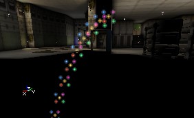
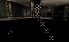
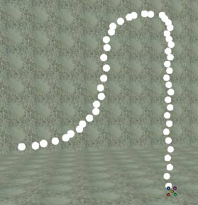
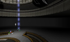
 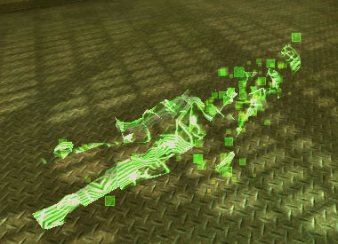 Another way to use skeletal mesh animation is to create a simple model that moves a bone in a pattern that you want an emitter to move in. This can be used to move emitters in more complex patterns than is otherwise possible with the PSE. The example below moves an emitter in a decreasing spiral that travels upwards.
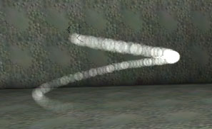
Complex movement patterns can also be achieved by using Anim Notifies to attach particles systems to bones. (See AnimNotify_Effect). While it is possible to use skeletal mesh animation without any new code (the spiral example did not use any new code for example) the system works best when coupled with game specific code. This is mainly do to the fact that SkeletalMeshActor must be an Actor that exists in the level. This makes it impossible to preview this type of particle system in Unrealed because characters do not move around or animate in the editor. Below is an example of attaching the dead green DeRes effect in UT2003:
DeResFX = Spawn(class'DeResPart', self, , Location);
if ( DeResFX != None )
{
   DeResFX.Emitters[0].SkeletalMeshActor = self;
   DeResFX.SetBase(self);
}
If you do not want to use code you can create a Pawn (or a subclass of Pawn if you are not using the UDNBuild) and set it to draw with a particular skeletal mesh and then animate that mesh using a scripted sequence. You will also have to attach the particle system to the pawn using the AttachTag and bHardAttach = true, if you want the particle system to move with the pawn. Also, make sure you place the pawn and particle system at the same location in the level.
Use Skeletal Location As
UseSkeletalLocationAs is used to tell the particles of the emitter how to spawn and move relative to the bones of the mesh.| UseSkeletalLocationAs | Description |
|---|---|
| Don't Use SkeletalMesh | Off. The skeletal mesh animation is not used at all. |
| Spawn at Vertex | The particles will spawn at bone locations but once the particle is spawned, it will not be effected by the mesh. The spiral example uses Spawn at Vertex which is why you see the trail in the path of the bone. |
| Move with Vertex | The particles will spawn at a bone location and will continue to be effected by the location of the bone but not the rotation. The spiral example from above would just look like a fat vertical white line moving around in a spiral. |
SkeletalMesh Actor
SkeletalMesh Actor is the Actor in the level whole skeletal mesh will be used to determine the spawning and motion of the particles in this emitter. In most cases this will be set in code. If you want to set this in the editor you will have type this in directly. First find the Name of the actor in the level by looking at the properties of this actor under Object or looking at the top of the properties window. In the SkeletalMesh Actor text window type the name of the actor.Skeletal Scale
Skeletal Scale is used to set the scale of the "mesh" used to spawn the particles. The mesh of the actor that the emitter is attached to is not exactly the mesh used to spawn the particles. For example if the mesh is scaled in the animation browser, this skeletal mesh animation system will use the size before the scale. You can use Skeletal Scale to match the size of scaled meshes or you can use it to intentionally make the size larger or smaller.RelativeBoneIndexRange
RelativeBoneIndexRange is used to determine which bones are used to for spawning particles. For all bones set this range from 0.0 to 1.0. If you only want some bones, set it to a sub range between 0 and 1. Which bones you get is dependent on how the bones are indexed in your model.Rotation
Spin
To make the particles Spin while they move, check Sping Particles and enter an X-Min and X-Max value at _Spins Per Second. The value you enter is the number of times per second the texture of the particle will spin. If X-Min and X-Max values are different, each particle will get a random value between Min and Max. You can also set to spin Counter Clock Wise or Clock Wise with the Spin CCW or CW slider. If you set it to something between 0 and 1, for example 0.7, there's 70% chance a particle will rotate Clock-Wise and 30% chance it'll rotate Counter-Clock-Wise. If SpinsPerSecondRange is 0.5 and SpinCCWorCW is 1, it'll look somewhat like the first animated gif. If you set Spin CCW or CW to 0.5, it'll do for example like on the second animated gif (on the second screenshot, some particles may suddenly switch from CCW to CW, but that's because otherwise the gif would require TOO many frames. This never happens in the editor.)
Start Spin
With Start Spin, you can set the rotation the particle has when it's spawned. You can also make the particle to have a random Start Spin, if you enter a different Min and Max value.Facing Direction
 Facing Direction determines how particles are oriented in the world. It is important to remember that this orientation is calculated BEFORE the spin of the particles is calculated. If there is any spin it will be applied after the facing direction making it difficult to see the effects of the facing direction. To illustrate the effect of this tool, I created a simple particle system effected by gravity. The texture on the particles is this arrow.
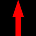 Facing Camera is the default and most common choice for facing direction. All the particles are billboarded facing the camera no matter where the camera is. This can be seen in the image below. The one confusing part about Facing Camera is that it flips the texture vertically. Another confusing aspect of this settings is that the size of particles has a constant aspect ratio because X size (from Start Size) is used to scale both X and Y. Y size is ignored when facing direction is set to Facing Camera.
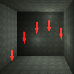
 Along Movement Facing Camera is fairly straightforward. The particles orient themselves so that the "up" of the texture is always facing the direction the particle is moving. The particle tries its best to also face the camera at the same time but it is hard at certain angles like looking along the direction the particle is moving. These two images illustrate the effect of this setting.
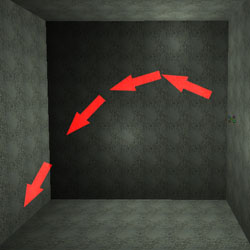
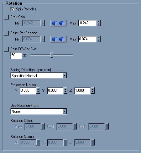
 Specified Normal is very simple; the particle normal is specified by Projection Normal. In the case of the first image the normal is straight up (0, 0, 1). The second image has a normal of (-0.5, 0.3, 1.0).
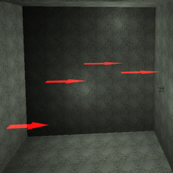
 Along Movement Facing Normal is like Along Movement Facing Camera but instead of facing the camera, the particles faces the specified Projection Normal. This is very useful for things like waterfalls where the particles should orient with its movement but not face the camera. The effects can be seen below.
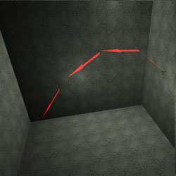
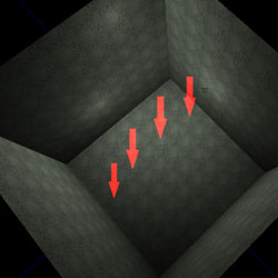
 Perpendicular to Movement orients the particles perpendicular to the movement direction. This has the unfortunate side effect that in some cases it rotates the particles 90 degrees mid flight. This can be seen in the image below.
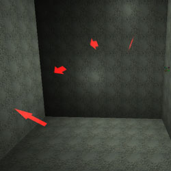
Projection Normal
This tool is enabled and used for the Specified Normal and Along Movement Facing Normal settings of Facing Direction.Use Rotation From:
You can also rotate the entire particle system for the particles using Use Rotation From . This affects the location and velocity, but not the acceleration. With Use Rotation From, you can set how to rotate it. If it's _None, the particle system is not rotated, cause the X-Axis, for example, to face the same direction as the main X-Axis in the editor. If Use Rotation From is set to Actor, the rotation of the Emitter Actor is used. If you set in Advanced bDirectional=True, the Emitter gets an arrow. The direction of that arrow is the X-Axis that now will be used for velocity and location. If Use Rotation From is set to Offset, the settings in Rotation Offset are used. There you can set how much the particle system has to Pitch, Yaw and Roll. If Use Rotation From is set to Normal, the settings in Rotation Normal are used for the rotation. Now, you can enter the direction of a plane, and the X-Axis will be perpendicular on that plane. For example on the first screenshot there is no Rotation Offset used, and the particles are moving with a Velocity of X = 500. On the second screenshot, they still have the same Velocity, but Use Rotation From is set to Offset and the Pitch+ of _Rotation Offset is set to 90.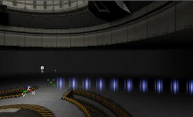
Revolution
 While Rotation is for rotating individual particles about their center, Revolution is for rotation particles about a fixed point in space. Using Revolution will cause the particles to change position.
Use Revolution
Checking Use Revolution will enable the use or revoltion.Revolution Center Offset
In general particles will revolve about the center of the particle system. Revolution Center Offset will allow you to change this so that particles rotate about a point other than the center of the particle system.Revolutions Per Second
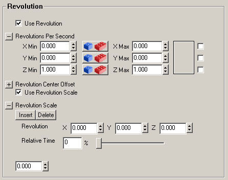
Revolutions Per Second specifies the number of revolutions per second around the specified axes.Use Revolution Scale
If Use Revolution Scale is true, the Revolution Scale will be used.Revolution Scale
This Revolution Scale is used as a multiplier for each of the axes of Revolutions Per Second range. Using Revolution Scale you increase or decrease the speed of revolution of particular axes over the lifetime of the particle. You can even reverse the direction of revolution by using negative numbers.Revolution Scale Repeats
Revolution Scale Repeats is the number of times the Revolution Scale will be additional repeated. Setting this to 0 will cause the revolution scale to happen just once. Setting this to 1 will cause the revolution scale to happen twice.Size
Uniform Size
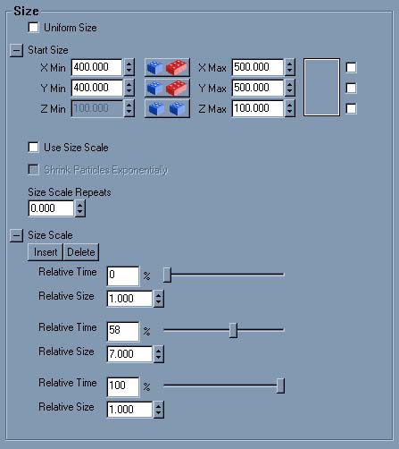
If Uniform Size is set to True, only the X is used for both U and V (or X, Y and Z for meshes). You may need this if you use a random Size if you want to preserve the aspect ratio.Start Size
The Start Size Range determinates the Size the particles will get when spawned. For Sprites, only the X values are useful if Facing Direction is Facing Camera. For all other settings of Facing Direction the X and Y can be used to change the width and height of the texture separately (but only if UniformSize is false). For Meshes, X, Y, and Z are used (but only if UniformSize is false). The default value is 100, the screenshots show X(Min) = X(Max) = 50, and X(Min) = X(Max) = 150.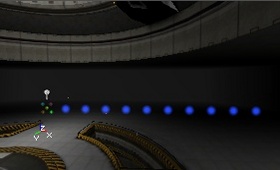
 If you enter a different X(Min) and X(Max) value, the particles will get a random Size.
Size Scale
The Size Scale works exactly the same as the Color Scale, only now you're working with a Size instead of a color. If you set Use Size Scale to True AND Shrink Particles Exponentially to True, the Particles will always shrink, and you don't have to add any SizeScales.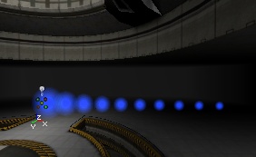
Collision
Use Actor Forces
Enabling Use Actor Forces lets actors with their force parameters set influence particles. (Any sort of actor works but pawns are the easiest because they already have their collision properties set just right.) The force parameters can be found by double clicking on the actor and selecting the Force category in the Properties window. ForceType must be set to FT_DragAlong and ForceScale must be greater than 0. To see a large effect set ForceScale > 50. ForceRadius can be set to anything but it might work well to set it to the CollisionRadius of the actor. Now with these parameters set, when this actor moves into the particles of this system, the actor will knock them radially away from the itself in the direction of movement. However, when the actor is stopped near the particles and the particles are moving, the particles will move towards the actor and circle around it. While this effect looks good, it is can be VERY slow. Sometimes it will run OK and then if the pawn moves just a little, or the view changes, the game might pause for several seconds while it recalculates the motion of all the particles.Use Collision
NOTE: Collision will not work if your coordinate system is set to "Relative" in the default code base. The Collision can make the particles realistically bounce on walls, floors or ceilings. It looks for example like the animated gif:
 If you have no Collision, the particles will just disappear in the wall:
 But if you set UseCollision to True, the particles will bounce on the wall. If they hit the wall perpendicularly, they will bounce back to from where they came as on the first screenshot, in any other case they'll bounce like on the second screenshot.
Damping Factor
The DampingFactor changes the velocity of the Particle every time it bounces on the wall. The Velocity gets multiplied by this factor. For example in the real world if you let a tennis-ball fall on the ground, it bounces less high every time it hits the ground again. On the following screenshots, there is an acceleration Z = -950, and a velocity of X = 500. The Particles are falling towards the ground, and then bounce. On every screenshot, the Z value of the DampingFactor is modified to show the difference. It's the Z value that's used, because in this case the particles are bouncing on the floor. If the DampingFactor is 1 they can keep and keep bouncing as long as they live, as shown on the first screenshot. If you make it lower than 1, for example 0.9, they'll bounce less high every time they hit the ground (this is most realistic).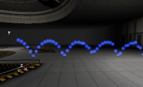
 If you make the DampingFactor higher than 1, for example 1.5, the particles will bounce higher and higher (1st screenshot). If you give a different Min and Max value, every particle will bounce randomly something between the Min and Max value (2nd screenshot).
Rotation Damping Factor
To use rotation damping factor you first have to check Use Rotation Damping. With Rotation Damping Factor, you can set the damping factor for the spinning particles, this works the same way as the Damping Factor of Collision, only it makes the particles spin slower or faster every time they bounce. For example if you make the Z-Min and Z-Max values of the Rotation Damping Factor 0, the spin will stop after the first bounce on the floor already because the Spins Per Second gets multiplied by 0. Note on the screenshot all the textures to have the same Rotation after the bounce: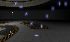
Extent Multiplier
The Extent Multiplier is multiplied by the Size of the particle, and this is used for the collision detection. This multiplied Size determinates where the colliding sides of the particles are, and as soon as that (invisible) side reached the surface, the particle will bounce. 0 represents the middle of the particle and 1 represents the normal size of the particle. For numbers larger than 1, the particle will bounce even sooner. This is useful because when particles are rotated the corners might hit the wall when Extent Multiplier is 1.Collision Planes
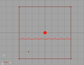
If you set Use Collision Planes to True, you can make invisible planes, where the particles will bounce on. The planed don't collide anything else, only the particles of that particular emitter. These planes are 1-sided which means the particle can go through it at one side but will bounce against it if it goes the other direction. You have to make the planes in the Collision Planes setting. For each plane, you can enter W, X, Y and Z. W is the distance from the plane to the center of the editor grid, and X, Y and Z determinate the normal of theplane and the that direction W moves the plane. You can also enter negative values, for example to get on the other side of the grid or to turn around the 1-sided direction. On the screenshots, the red dot represents the center of the editor grid, the grid itself is 256 units, and the red line shows the (invisible) plane. The small red triangles point into the direction the particles can go through the plane. On the first screenshot, W=256, X=0, Y=1 and Z=0. The particles can go to the south until they bounce against the wall, and when going north again, they'll bounce against the plane. On the second screenshot, W is changed to -256 and Y to -1, so the direction turns around, and the particles will bounce against the other side of the plane instead.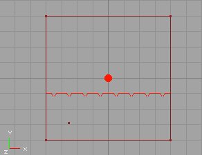
Max Collisions
If you set Use Max Collisions to True, the particle will die when it bounced the (random) number of times you enter in MaxCollosions, no matter what the lifeTime is.Spawn From Other Emitter
With SpawnFromOtherEmitter, you can make something to get spawned at the location where the particle bounces, for example sparks leaving a glowing mark where they hit, or rippels in shallow water. For this to work, you have to make a second emitter inside of the same emitter actor, and select that emitter is Spawn From Other Emitter. The particles of this new emitter are the ones that will be spawned at the location of bouncing particle when it bounces (this is subtly different from the location of the bounce particularly if you have a large Extent Multiplier). For the new emitter, set Respawn Dead Particles and Automatic Spawning to False. The reason for this is, otherwise these particles may also get spawned at the wrong moment at the location of the particle system in the world. Then, in Spawn Amount Range, enter the number of particles you want to get spawned when the bouncing particle hits the surface. This must be at least 1 for the anything to happen.Spawned Velocity Scale
If you check Use Spawned Velocity Scale, you can also give the particles that get spawned when it bounces a velocity. You can set this Velocity in the Spawned Velocity Scale settings: you can give Minimum and Maximup X, Y and Z settings. If the particle bounces, the spawned particles only get the velocity in the normal direction on the surface. The best way to use this to give the mins and maxs of X, Y, and Z all the same positive value so that the they will travel in the direction of the normal (If you give X, Y, and Z negative values the spawned particles will more towards the surface they bounced off). Spawned Velocity Scale can be used very well with Facing Direction. If you set Facing Direction to 'Perpendicular To Movement' and set the spawned velocity to a very small value (like 1.0) the secondary particles will be aligned with the surface they bounced off. This works very well for impact marks.Sounds
 Sounds can be played when particles are spawned and also when they collide with the world.
Spawning Sound
Spawning sounds can be enabled by setting the Spawning Sound pull down to anything other than Don't Use Spawning Sounds. The other options for Spawning Sound are as follows:- Linear Global / Linear Local - These both play though the sounds in a linear order when particles are spawned. Every time a particle is spawned, the next sound in the Sound Array in the range specified by Spawning Sound Index is played.
- Random - plays a random sound in the Sound Array in the range specified by Spawning Sound Index.
Spawning Sound Index
Spawning Sound Index selects the range for which sounds will play. When you specify a sound range using Spawning Sound Index, the Min and Max must be different numbers. If they are the same, Min=0 and Max=0 for example, all the sounds in Sound Array will be used.Spawning Sound Probability
Spawning Sound Probability is a range for the probability that a sound will play on spawning. One might wonder, "Why a range when this is already a probability?" I wonder the same thing.Collision Sound
Collision sounds can be enabled by setting the Collision Sound pull down to anything other than Don't Use Collision Sounds. The other options for Collision Sound are as follows:- Linear Global - plays the sounds in the Sound Array in order, in a loop without, regard to the particle's lifetime. This loop is per particle and so if a burst of particles is spawned at the same time, and this burst hits a wall, all the particles will play the same collision sound.
- Linear Local - is like Linear Global except that the loop for each particles is reset at the end of it's lifetime. This mean that if the Sound Array contains the sounds "Boing!", "Bop!", and "Thud!", in that order, particles will always start with "Boing!". If a particle only collided with the world twice, the first time it collides in its next life, it will not go "Thud!", as it would in the case of Linear Global.
- Random - plays a random sound in the Sound Array.
Collision Sound Index
Collision Sound Index selects the range for which sounds will play. When you specify a sound range using Collision Sound Index, the Min and Max must be different numbers. If they are the same, Min=0 and Max=0 for example, all the sounds in Sound Array will be used.Collision Sound Probability
Collision Sound Probability is a range for the probability that a sound will play on collision. One might wonder, "Why a range when this is already a probability?" I wonder the same thing.Sound Array
Sound Array is an array of sounds that contain Sound, Radius, Pitch, Volume, and Probability.- To set the Sound, select a sound in the Sounds browser and click Use.
- The Radius is in stand unit for sound radii which is something other than Unreal units. 64 seems to be a good value.
- For Pitch, 1.0 is the default pitch.
- The Volume setting only accepts values between 0.0 and 1.0. 1.0 is the standard volume and it can only be made more quiet.
- Probability is the chance that this sound will play if it is told to play. The sound will be told to play based on Spawning Sound Probability or Collision Sound Probability.
Mesh
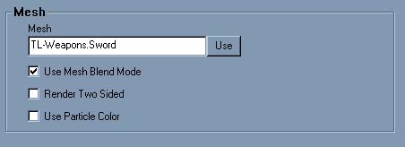
Mesh
This is very similar to the Texture field. In the Static Mesh browser select the mesh you want to use for this mesh emitter and click Use.Use Mesh Blend Mode
If this is true, the blend mode of the mesh is used. This means that the particles will look just like they do when you drop them in the level. If this is false, the particles will use the blend mode defined in the Texture category.Render Two Sided
If this set, the mesh will render all triangles two sided. This is usefull only if UseMeshBlendMode is false.Use Particle Color
If this is set, the mesh will use the settings in Color/Fading?. This is only usefull if UseMeshBlendMode is true.Spark
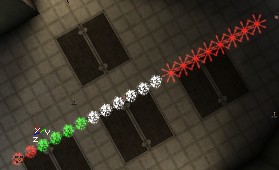
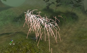
 This ParticleEmitter generates sparks, for example the kind of sparks you see when someone's welding. This emitter turns it's Texture into one thin line with the colors of the texture. Settings such as Acceleration, Start Velocity, and Start Location still work on it, but Collision, Rotation, Size, etc... don't work on it because the particles are just lines. Texture still works to color the particle but because it is just a line the entire texture can not be seen. Things such as the Color Scale and Fading work, but these work per segment so you might not get the look you expected. On the screenshot: a random Start Location and a subtle red Color Scale on a white texture.
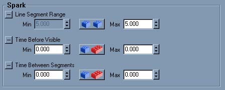
 To get a working Spark Emitter, add one the same way you'd add a Sprite or Mesh Emitter, and first give the it Velocity or Acceleration and then go to it's Spark properties. There set the Min and Max value of Time Between Segments to 1, you'll see the emitter working already.
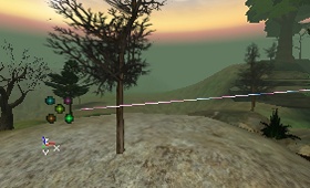
Line Segment Range
Line Segments Range this determinates how long the sections of the lines of the sparks will be, and also how visible they are. You can also make the length to be random if you enter a different Min and Max value. If you make this setting too high or too low (depending on other settings), the Spark Emitter will not work. The first screenshot has Min = Max = 5, the second screen has Min = Max = 3. A setting of 5 most of the times works the best. 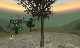
Time Before Visible
Time Before Visible Range doesn't seem to do too much.Time Between Segments
The effect of Time Between Segments is best visible if you let the line to be curved, when you use some acceleration. Time Between Segments Range determinates in how many segments the line should be divided. If this settings is low, for example 0.1, the line will be divided into a lot of segments so the curve looks smooth (first screenshot). If it's high (for example 0.5), you'll see the line broken into segments. (second screenshot). A higher Time Between Segments means less particles and thus better performance, but it doesn't look as good.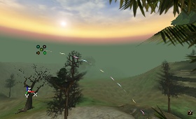
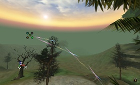 For low Time Between Segments settings, there will have to be more particles created (every segment of the line is a particle), so you might have to set Max Particles and to something higher before it looks good. A very high Max Particles might create something like this (again with low and high Time Between Segments)
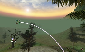
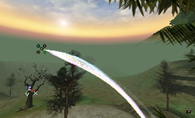
Beam
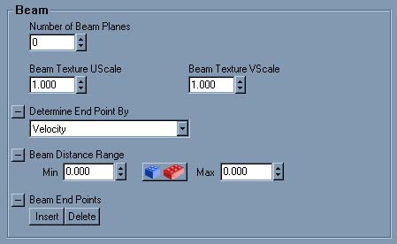 Beam Emitters are very useful to create lightning and other such things. The emitter stretches the chosen Texture into a beam with High Frequency Points and Low Frequency Points. There must be at least two of each to make the lightning work. Each particle will be such a beam, and once created a particle never moves. The way to get the lightning moving is to create a new beam all the time while the old one gets destroyed, or to make the lightning flash with a Color Scale. Normally, the beam is only one angular line, but you can also give it branches.
Getting started: Given a new beam emitter, leave all the settings at default, and add some Velocity and you will start to see something. The length of the beams depends on the magnitude of the Velocity and the Lifetime.
Beam Emitters are very useful to create lightning and other such things. The emitter stretches the chosen Texture into a beam with High Frequency Points and Low Frequency Points. There must be at least two of each to make the lightning work. Each particle will be such a beam, and once created a particle never moves. The way to get the lightning moving is to create a new beam all the time while the old one gets destroyed, or to make the lightning flash with a Color Scale. Normally, the beam is only one angular line, but you can also give it branches.
Getting started: Given a new beam emitter, leave all the settings at default, and add some Velocity and you will start to see something. The length of the beams depends on the magnitude of the Velocity and the Lifetime.
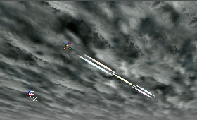
You may recognize the 5 colored dot texture on this beam. If you want, you can change it in something better in Texture. In the following examples a square, white texture is used. To make the lightning look much better, use a better texture for it. The texture for the lightning should be rotated 90�, like this:
 The best way to make the lightning to flash realistically is to use a [[#ColorScale][color scale]. This will make the whole beam change it's color during it's LifeTime. On the animated screenshot, there are 2 [[#ColorScale][color scales]: orange and yellow and the lifetime of the particles is 0.6 seconds. You can also use Fade In and Fade Out to make a flashing effect.
Number of Beam Planes
This option determinates how many planes the Beam is made of. 0 and 1 mean the same: only one sheet. The screenshots show 0, 3 and 10.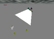
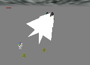
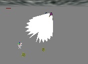
Beam Texture Scale
By default, the texture is repeated only once for the Beam. In Beam, with BeamTextureUScale you can set how many times to repeat the texture in the length of the Beam, and with BeamTextureVScale how many times to repeat it in the width: it's repeated 4 times on the screenshots.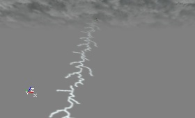
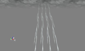
Determine End Point By
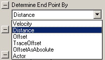 This property sets what determines the EndPoint of the beam. The StartPoint is determined by the location of the Emitter actor and the settings in Location. There's more about StartPoints for beams later.
Velocity is the default setting. With this selected the end point is determinated by the Velocity of the particle and the Lifetime. The length of the beam is then determinated by the StartVelocityRange values and the Lifetime of the particles. The direction of it is determinated by the X, Y and Z values of the StartVelocityRange. You can again use random values, so for example if X(Max) = Y(Max) = Z(Max) = +1000 and X(Min) = Y(Min) = Z(Min) = -1000, each Beam will be anything random between this. It'll do almost exactly the same as on this animated gif below. You'll be able to see more than one Beam now, because MaxParticles is set to 10 by default. Also, lightnings normally only goes straight towards the ground, so only using negative Z values for StartVelocityRange is useful.
This property sets what determines the EndPoint of the beam. The StartPoint is determined by the location of the Emitter actor and the settings in Location. There's more about StartPoints for beams later.
Velocity is the default setting. With this selected the end point is determinated by the Velocity of the particle and the Lifetime. The length of the beam is then determinated by the StartVelocityRange values and the Lifetime of the particles. The direction of it is determinated by the X, Y and Z values of the StartVelocityRange. You can again use random values, so for example if X(Max) = Y(Max) = Z(Max) = +1000 and X(Min) = Y(Min) = Z(Min) = -1000, each Beam will be anything random between this. It'll do almost exactly the same as on this animated gif below. You'll be able to see more than one Beam now, because MaxParticles is set to 10 by default. Also, lightnings normally only goes straight towards the ground, so only using negative Z values for StartVelocityRange is useful.
Distance does the same as Velocity, but the StartVelocityRange only determines the direction of the beam. The length is set with Beam Distance, in editor units. Offset allows you to determinate the EndPoint in relative coordinates. You have to enter these coordinates in Offset, inside BeamEndPoints[0]. To get this, first expand Beam End Points and press the Insert button.
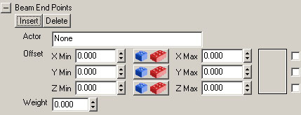
In Offset, enter the X, Y and Z coordinate range for the EndPoint of the Beam. The coordinates are relative to the StartPoint (most of the times this is the Emitter actor), so for example X = 0, Y = 0, Z = -1000 means the EndPoint will be 1000 units below the StartPoint. Before it works, you also have to set Weight to something larger than 0. You can again use different Min and Max values if you want a random Location for the EndPoint. You can add more Beam End Points, and then the Beam will use one of these Beam End Points by random. With Weight, you can set the importance of each Beam End Point, this is the probability that it'll be used. If you give all the Beam End Points a Weight of 1, the chances will be equally divided. If for the Offset X = Y = Z = 0, the EndPoint and the StartPoint the same, so there won't be a Beam. You can use this if you want the lightning to strike only a few times and to be invisible for the rest of the time. Then you can give the Beam End Point with this 0-Offset a high Weight, so the lightning is most of the times invisible. TraceOffset does the same as Offset, but if there is a solid surface in the way the lightning will hit against it, instead of going to the actual end point. TraceOffset does not work well in combination with the relative coordinate systems. OffsetAsAbsolute does the same thing as Offset but interprets the offset range as world coordinates instead of relative coordinates. So if X = Y = Z = 0, the beam end point would be at the origin. Actor lets you make the beam go to a certain actor. This also uses [[#BeamEndPoints][Beam End Points], but this time, you have to fill in the Actor Tag property (and not the Offset property). The lightning will go towards the actor you gave that Tag (in the Event properties of that actor). If you want the lightning to go randomly towards different actors, you have to add more Beam End Points, and in each Beam End Points enter a different Actor Tag. Of course also give the actors these Tags. If you'd give three trees the SAME tag and use only the first Beam End Point, it won't work, the lightning will go to only one of the trees then. Again you have to give each of the Beam End Points a Weight higher than 0, that is the chance this Beam End Point will be used. For example if there are three trees, with Tags FullTree, FullTree2 and FullTree3, and you want the lightning to strike each of the trees randomly, but to strike FullTree3 twice as much as the other trees, give the following properties to the emitter:
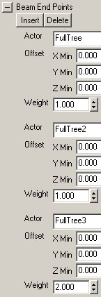
 If the actor is moving, the Beam will follow it:
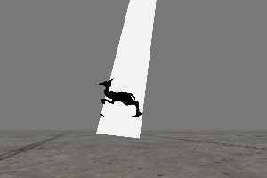
Beam Distance Range
This determines the length of the beam when Determine End Point By is set to Velocity.Beam End Points
This determines the various end points of the beam when Determine End Point By is set to Offset, Actor, and TraceOffset.Trigger Actor End Point
If Trigger Actor End Point is true, the beam will trigger the actor it draws to. This only works if Determine End Point By is set to Actor and there are valid actor tags in the the Beam End Points array. For example, this can be used to spawn impact effects for lighting at the strike point.Beam Noise
 Here you can give the beam noise. You can give High Frequency Points and Low Frequency Points. Both do exactly the same, but you can use them independent for example to give the lightning a lot of small bends inside a few large bends. There must be at least 2 High Frequency Points (and 2 Low Frequency Points), these represent the start point and end point. If you set it to 0, the editor crashes. If you set it to 1, there will be no beam. If it's 2, the beam will always be straight. If High Frequency Points is 3 (and Low Frequency Points is 2), there will be 1 bend in the half of the beam. The higher the value, the more bends. You can determinate the size of the bend with High or Low Frequency Noise Range by entering Min and Max values for X, Y and Z there. This way you can set the direction of the bend, the size of it, and you can make it to be random. Actually, you have to make it random, otherwise it'll not work the way you want. For example if High Frequency Noise Range has Y(Max) = 1000 and Y(Min) = -1000 and there are 4 High Frequency Points, it'll look like the screenshot. 1 particle will not change during it's lifetime, so to get the lightning moving make sure the lifetime is short enough for new particles to get spawned fast enough.
 You can also make a High Frequency Scale. This is similar to the Color Scale, Size Scale, etc..., only the High Frequency Scale determinates the High Frequency Noise Range on the different places of the beam. You can see the effect of the High Frequency Scale best on beams with a lot of High Frequency Points, so set it to for example 100. Without the High Frequency Scale, the whole beam has the same Noise Range everywhere:
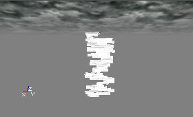 To enable the High Frequency Scale, first set Use High Frequency Scale to True, and then add a High Frequency Scale, the same way as you added Color Scale: expand the High Frequency Scale Factors and press the Insert button until you have enough scale factors. The frequency scale multiplies the High Frequency Noise Range (X, Y and Z separately), and Relative Length determinates the location on the beam where you want this multiplier to happen. 100% represents the length of the whole beam. If you set Relative Length of the first High Frequency Scale Factor to 70%, the first 70% of the Beam will have the scale of that High Frequency Scale Factor, and if you then set the Relative Lentgh of next High Frequency Scale Factor to 100%, the remaining 30% will get multiplied by the this Frequency Scale. On the screenshot the first Frequency Scale is 1 for X, Y and Z, and the second Frequency Scale is 10 for X, Y and Z.
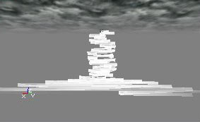
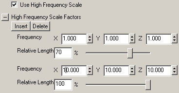 You can use High Frequency Scale Repeats to repeat the scale 1 or more times, just the same way as for the Color Scale and the other scales. For example it looks like this if High Frequency Scale Repeats = 2.
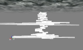 The Low Frequency settings do exactly the same as the High Frequency settings. Low frequency and high frequency work independently from each other, and can be used "through" each other. For example, you can use a lot of small High Frequency Points, and a few, very large, Low Frequency Points. Then the beam will have a few large bends, and a lot of small bends at the same time, as shown on the screenshot:
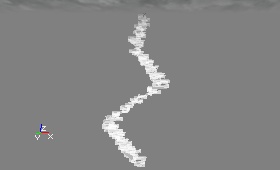 NoiseDeterminesEndPoint allows the noise applied to the beam to also affect its endpoint, which in most cases, it already does. Sometimes, however, the location of the endpoint is locked-- if the DetermineEndPointBy setting is PTEP_Actor, for example. In this case the endpoint will be set to the center point of the specified actor. However, this might not be the desired effect. It might look odd to see lightning strike the exact same place repeatedly. Checking this box will allow the beam to strike the desired actor but in a more random fashion. If the beam were striking a triggerable actor, allowing the noise to determine the endpoint will not stop the actor from triggering, even if the beam does not visually strike that actor. Note that this might result in visual glitches if the amount of noise is great. For example, let's say your beam is supposed to strike a tree and set off a fire particle system. However, it will look strange if a lightning bolt strikes the ground and tree 40 feet away from the impact bursts into flame. Reducing the amount of noise on the beam would fix this problem.
Dynamic High Frequency Noise is used to make the beam actually move over the course of its lifetime. The feature uses the High Frequency Points described above. The only drawback of dynamic noise is that it only works on the first beam in a beam emitter. If you have more than one beam, the dynamic noise will not apply to the additional beams. The movement of the high frequency points is calculated on a time interval determined by Dynamic Noise Points Update Time. If you want the beam to updates continuously set Dynamic Noise Points Update Time to 0 or some very small number. Each timestep the high frequency points between the min and max of Dynamic High Frequency Noise Points will be skewed by a random amount based on Dynamic High Frequency Noise. The high frequency points start at index 0 at the start of the beam and end at 1 less than the total number of points. If the beam has 20 high frequency points and Dynamic High Frequency Noise Points is set from 0 to 10, only have the beam will move dynamically.
NoiseDeterminesEndPoint allows the noise applied to the beam to also affect its endpoint, which in most cases, it already does. Sometimes, however, the location of the endpoint is locked-- if the DetermineEndPointBy setting is PTEP_Actor, for example. In this case the endpoint will be set to the center point of the specified actor. However, this might not be the desired effect. It might look odd to see lightning strike the exact same place repeatedly. Checking this box will allow the beam to strike the desired actor but in a more random fashion. If the beam were striking a triggerable actor, allowing the noise to determine the endpoint will not stop the actor from triggering, even if the beam does not visually strike that actor. Note that this might result in visual glitches if the amount of noise is great. For example, let's say your beam is supposed to strike a tree and set off a fire particle system. However, it will look strange if a lightning bolt strikes the ground and tree 40 feet away from the impact bursts into flame. Reducing the amount of noise on the beam would fix this problem.
Dynamic High Frequency Noise is used to make the beam actually move over the course of its lifetime. The feature uses the High Frequency Points described above. The only drawback of dynamic noise is that it only works on the first beam in a beam emitter. If you have more than one beam, the dynamic noise will not apply to the additional beams. The movement of the high frequency points is calculated on a time interval determined by Dynamic Noise Points Update Time. If you want the beam to updates continuously set Dynamic Noise Points Update Time to 0 or some very small number. Each timestep the high frequency points between the min and max of Dynamic High Frequency Noise Points will be skewed by a random amount based on Dynamic High Frequency Noise. The high frequency points start at index 0 at the start of the beam and end at 1 less than the total number of points. If the beam has 20 high frequency points and Dynamic High Frequency Noise Points is set from 0 to 10, only have the beam will move dynamically.
Beam Branching
 To make good looking lightning effects, you can give beams branches. If this is used correctly, you can get a very cool and realistic lightning. It works like this: you have to create more than one BeamEmitter (inside the same Emitter). Then you can tell the first BeamEmitter to use the second BeamEmitter for the branches. Then again, you can tell the second BeamEmitter to use a third one for sub-branches, and so on. The Max Particles setting is also the maximum number of branches.
First add multiple beam emitters and give each Emitter the properties you want. Make the first one big, and set it's Max Particles to 1. Make the second and third one smaller; they're for the branches. Give them many more Max Particles, for example 10 or 25. Also, setRespawnDeadParticles to False for all branches, and set AutomaticInitialSpawning to False, otherwise the branches might get spawned at the start point of the emitter itself instead of the new start point they get when they become branch. Also, make sure the beam emitters that will get branches, have a lot of Beam Noise. The branches will appear in the bends only, so if there aren't enough High Frequency Points, there will not be a place for all the branches! You can of course make the noise very subtle, so you won't notice it, only the number of High Frequency Points is important; the more the better.
To make good looking lightning effects, you can give beams branches. If this is used correctly, you can get a very cool and realistic lightning. It works like this: you have to create more than one BeamEmitter (inside the same Emitter). Then you can tell the first BeamEmitter to use the second BeamEmitter for the branches. Then again, you can tell the second BeamEmitter to use a third one for sub-branches, and so on. The Max Particles setting is also the maximum number of branches.
First add multiple beam emitters and give each Emitter the properties you want. Make the first one big, and set it's Max Particles to 1. Make the second and third one smaller; they're for the branches. Give them many more Max Particles, for example 10 or 25. Also, setRespawnDeadParticles to False for all branches, and set AutomaticInitialSpawning to False, otherwise the branches might get spawned at the start point of the emitter itself instead of the new start point they get when they become branch. Also, make sure the beam emitters that will get branches, have a lot of Beam Noise. The branches will appear in the bends only, so if there aren't enough High Frequency Points, there will not be a place for all the branches! You can of course make the noise very subtle, so you won't notice it, only the number of High Frequency Points is important; the more the better.
Use Branching, Branch Emitter
Then go to the Beam Branching properties of the first beam emitter. Set Use Branching to True, and set Branch Emitter to one of the first other beam emitter. Now the beam emitter you selected will be used for the branches.Branch Probabilty
With BranchProbability, you can set the chance of branches to appear. If you set both Min and Max to 1, all the branches will be there (this is, the number of branches that you set in Max Particles). If you set Min and Max to 1, the branches may appear only at the top of the main beam depending on the number of beams on the branching emitter. This is because each chance the beam gets to spawn, it will spawn. If Min=0 and Max=1, the branches will be divided over the whole beam but may not use all the beams of the branching emitter. You have to experiment a little with this setting to find the best result.Branch Spawn Amount Range
In Branch Spawn Amount Range, both Min and Max have to be larger than 1, as soon as you make one of them smaller than 1, there won't appear any branches at all. The Branch Spawn Amount is the number of beams to spawn at each high frequency point. When this is 1, there will be at most 1 branch at each point. If this is 10, there will be up to 10 branches coming off each point.Branch High Frequency Points
This is the range of high frequency points the branches of the beam will be spawned on. The high frequency points are indexed starting with 0 at the beam's origin and continuing up to the number of high frequency points. The Max of this can be set well beyond the number of the high frequency points so if you don't want to think about this setting make sure the Min is 0 and the Max is very large, like 1000.Linkup Lifetime
If Linkup Lifetime is False, the branches may stay behind while the large beam is somewhere else already. This happens when the branch has a bigger lifetime. If you set Linkup Lifetime to True, this problem is gone because the branches will live as long as the main beam, no matter what lifeTime they have. Only make sure Respawn Dead Particles is False for the branches then, otherwise they get spawned at the wrong place when Linkup Lifetime is True. For example, here the main beam is red, it has 12 Low Frequency Points, and 60 very small High Frequency Points that can be used as spawnpoints for the 25 green branches.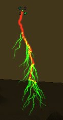 You can now do the same in the Beam Branching properties of the second beam emitter (the one that was used as branch). In this emitter also set Use Branching to True, and set Branch Emitter to the last emitter. This way, the branches get sub-branches themself. Note that not all the branches will get sub-branches, especially the ones closest to the top will get the least. Also, if Max Particles is 10 for the sub-branches, there will be 10 sub-branches total, and not 10 for every branch. For example, this emitter has 10 sub-branches (pink).
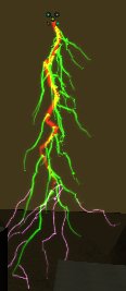
Trigger
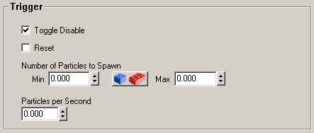 Triggering allows you to change the behavior of an emitter when it is triggered. You can trigger an emitter just like everything else in Unrealed by setting the Tag of the Particle System to be that of an Event of a trigger. It is important to note that the Tag is not specified per emitter but for the entire particle system. Each emitter can configure how it handles the trigger differently but they will all receive the same trigger event at the same time.
Triggers are use mainly to turn emitters on and off in different ways. This trigger system provides good ways to turn emitters on but it unfortunately does not provide a very smooth way to turn emitters off.
Triggering allows you to change the behavior of an emitter when it is triggered. You can trigger an emitter just like everything else in Unrealed by setting the Tag of the Particle System to be that of an Event of a trigger. It is important to note that the Tag is not specified per emitter but for the entire particle system. Each emitter can configure how it handles the trigger differently but they will all receive the same trigger event at the same time.
Triggers are use mainly to turn emitters on and off in different ways. This trigger system provides good ways to turn emitters on but it unfortunately does not provide a very smooth way to turn emitters off.