UDN
Search public documentation:
SettingUpVehicles
日本語訳
中国翻译
한국어
Interested in the Unreal Engine?
Visit the Unreal Technology site.
Looking for jobs and company info?
Check out the Epic games site.
Questions about support via UDN?
Contact the UDN Staff
中国翻译
한국어
Interested in the Unreal Engine?
Visit the Unreal Technology site.
Looking for jobs and company info?
Check out the Epic games site.
Questions about support via UDN?
Contact the UDN Staff
UE3 Home > Gameplay Elements > Setting Up Vehicles
Setting Up Vehicles
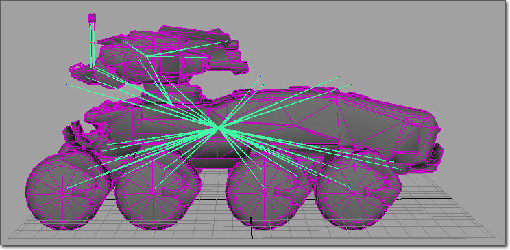
Modeling Vehicles - Setup and Rigging
- The root bone must be weighted to the main rigid chassis of the vehicle.
- The vehicle should point down the +X axis and have +Z as up, and the root `chassis' bone should point down the +X axis and have +Z as up as well. It is a good idea to get the vehicle pointing in the right direction before adding any bones.
- Any other bones for wheels and suspension should be direct children of the chassis bone. Do not make wheel bones children of suspension bones - leave them as children of the chassis.
- Place each tire bone where you want the wheel to rotate (both roll and steering). One axis of the bone should point along the roll axis and another should point along the steering axis (you can tell the engine which axis to use once it has been imported and you are setting up the AnimTree).
- When exporting the vehicle, make sure the wheel bones are moved down to the fullest extension of the suspension.
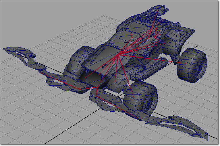
- Any weapons will need bones to be able to rotate, both Pitch and Yaw (can be the same bone for both or separate). For vehicle with multiple seats for passengers, each seat should have a bone which the passenger occupying that seat will be attached to (if visible). Also, the camera(s) and any effects (such as muzzle flashes and spawning projectiles, thruster effects, damage effects, etc.) used by the vehicle will need sockets to be attached to. In many cases, these will not require bones at the exact location here the socket will be located, but it often makes setting up the sockets much quicker if they are.
Vehicle Export
Vehicle Import and Setup
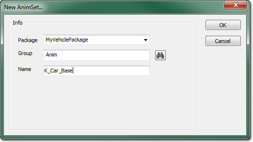
 Textures and materials for the vehicle should also be imported, set up, and assigned to the skeletal mesh. In the AnimSet Editor, you can create a new AnimSet for the vehicle from the File menu by choosing New AnimSet... and then providing a Package, Group (optional), and Name.
 Then, the .PSA file containing any animations for the vehicle should be imported into the vehicle's AnimSet by choosing Import PSA..., again from the File menu in the AnimSet Editor.
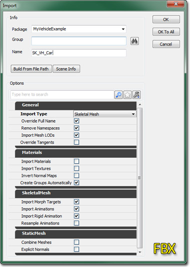
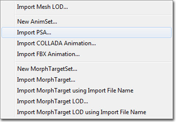 If you are using the .FBX file format, you would choose Import FBX Animation... here, instead, to import your animations.
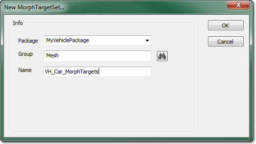
If the vehicle has any morph targets, those can be imported through the AnimSet Editor as well. First, create a new MorphTargetSet by choosing New MorphTargetSet from the File menu and the provide a Package, Group (optional), and Name.
If you are using the .FBX file format, you would choose Import FBX Animation... here, instead, to import your animations.
If the vehicle has any morph targets, those can be imported through the AnimSet Editor as well. First, create a new MorphTargetSet by choosing New MorphTargetSet from the File menu and the provide a Package, Group (optional), and Name.
 Then each individual morph target can be imported into that morph target set by choosing Import MorphTarget from the File menu.
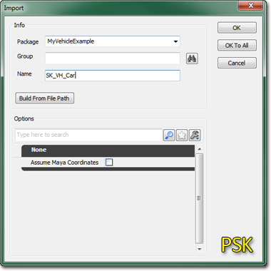
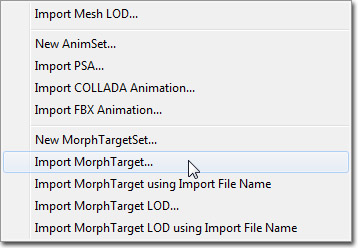 This option provides the ability to import .PSK or .FBX files conatining a morph target.
Create A Physics Asset
Once you have imported your vehicle mesh into the engine, you need to create a Physics Asset for it, to define the collision shape for it. To do this you need to use PhAT (the Physics Asset editing Tool). The only body that is important for a Physics Asset used with a vehicle is the root `chassis' bone. You do not need to create physics bodies for any other bones - you don't need to create joints for wheels for example. Wheel simulation is all handled by the vehicle physics code. Only the chassis body will be created as a physics object, and used for the vehicle collision. PhysicsAssets are used for line check and player collision against the vehicle though, so you may want to create collision shapes for other bones to get more accurate collision - particularly if those bones are going to move (doors, flaps, turrets etc). The mass and inertia of a vehicle in the game is calculated based on the volume of the chassis collision geometry, and the Density property of the PhysicalMaterial applied to the chassis BodySetup. To modify the mass of a vehicle in the game you can either modify the PhysicalMaterial, or adjust the MassScale property of the chassis BodySetup.Create An Anim Tree
Although you may not be playing animation on your vehicle, you will still need to create an AnimTree for it to work properly. This is because AnimTrees also contain SkelControls to move individual bones around procedurally in the game. The UE3 vehicle system uses a special type of bone controller to move the wheel bones to match the underlying simulation. You can find more information on wheel SkelControls on the Using Skeletal Controllers page. See the AnimTree Editor User Guide for more information about basic AnimTree setup and using the editor.Setting Up Wheels
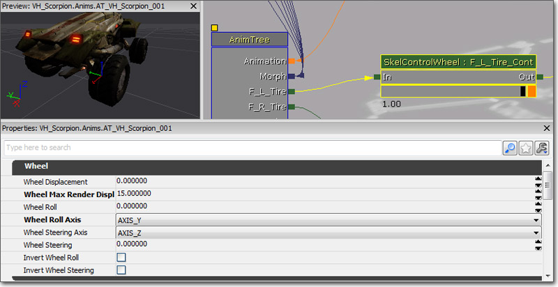 The `WheelDisplacement', `WheelRoll', and `WheelSteering' settings are simply visual so you can see, in the editor, that things are moving the correct direction in the correct axis. They do not actually change the performance or limitations of the vehicle.
The `WheelMaxRenderDisplacement' setting will set the upper limit of translation in the Z axis. This will determine the range of movement for the suspension. So enter values into `WheelDisplacement' to visually determine where you want the upper most limit of travel for the wheel. Then enter that final value into `WheelMaxRenderDisplacement' to set it as a limit. While using the vehicle in game, the wheels will travel up and down between 0 and the number you specify in `WheelMaxRenderDisplacement'. The Roll and Steering axis can be changed and inverted using the remaining settings.
You need to set the ControlName property of the SkelControlWheel. This will be passed to the simulation so it knows which control to update as you drive around.
The `WheelDisplacement', `WheelRoll', and `WheelSteering' settings are simply visual so you can see, in the editor, that things are moving the correct direction in the correct axis. They do not actually change the performance or limitations of the vehicle.
The `WheelMaxRenderDisplacement' setting will set the upper limit of translation in the Z axis. This will determine the range of movement for the suspension. So enter values into `WheelDisplacement' to visually determine where you want the upper most limit of travel for the wheel. Then enter that final value into `WheelMaxRenderDisplacement' to set it as a limit. While using the vehicle in game, the wheels will travel up and down between 0 and the number you specify in `WheelMaxRenderDisplacement'. The Roll and Steering axis can be changed and inverted using the remaining settings.
You need to set the ControlName property of the SkelControlWheel. This will be passed to the simulation so it knows which control to update as you drive around.
Setting Up Suspension Bones
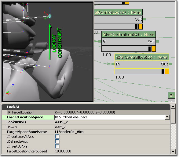
As well as having a control to move the wheels as you drive, you may want to add some additional controls to bones that control suspension arms. There is a type of SkelControl called a `look at' controller, which tells the bone to always point one axis towards another object, bone, or point in space. This node is used to control suspension bones.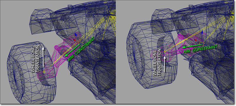
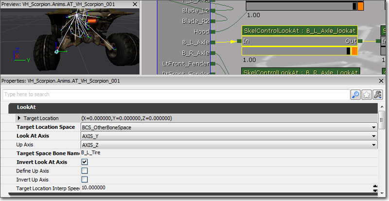 The blue diamond shape is the aiming target. The `TargetLocationSpace' setting determines what the aim target is relative to: itself, its parent, actor space, world space, or in this case, another bone. Enter the name of the bone you want to aim at in the `TargetSpaceBoneName' setting. The `Target Location' setting will offset the position of the aim target relative to its `Target Location Space' setting. You can also offset the aim by chaining a SkelControlSingleBone node after the LookAt node to offset the rotation of the suspension bone.
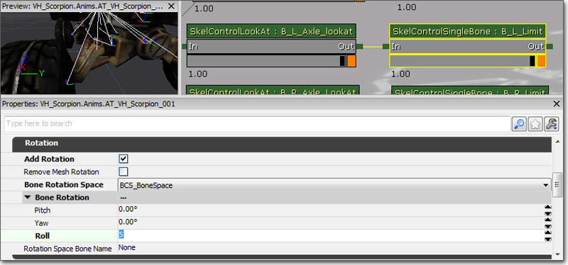 You can change or invert the LookAtAxis or UpAxis if it was aligned different in your 3D package. Depending on the complexity of your suspension, you could use the LookAt nodes and SingleBone nodes to create pistons and other connected moving parts.
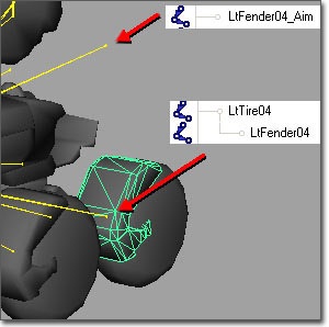
LookAt nodes can also be used to cancel out rotation on parts connected to the wheel, such as fenders, that need to rotate with the steering and move with the suspension, but should not spin forwards or backwards. To do this, add a bone, parented under the wheel bone, but located in the exact same place. Bind the fender mesh to this bone. Add another bone directly above wheel bone. This will be what the fender will aim at. In the AnimTree, add a LookAt constraint to the fender bone, aiming at the fender-aim bone. In the LookAt node settings, set both the LookAt Axis and Up Axis to Z. The fender bone should now move with the wheel bone during suspension travel, and steering, but will not spin.
You can change or invert the LookAtAxis or UpAxis if it was aligned different in your 3D package. Depending on the complexity of your suspension, you could use the LookAt nodes and SingleBone nodes to create pistons and other connected moving parts.
LookAt nodes can also be used to cancel out rotation on parts connected to the wheel, such as fenders, that need to rotate with the steering and move with the suspension, but should not spin forwards or backwards. To do this, add a bone, parented under the wheel bone, but located in the exact same place. Bind the fender mesh to this bone. Add another bone directly above wheel bone. This will be what the fender will aim at. In the AnimTree, add a LookAt constraint to the fender bone, aiming at the fender-aim bone. In the LookAt node settings, set both the LookAt Axis and Up Axis to Z. The fender bone should now move with the wheel bone during suspension travel, and steering, but will not spin.
Setting Up Damage Nodes
Vehicles extending from the UTVehicle class can make use of the localized damage system. This allows vehicles to show progressive damage in the locations where the damage is being done. The system makes use of morph targets as well as special skeletal controllers, the UTSkelControl_Damage, UTSkelControl_DamageHinge, and UTSkelControl_DamageSpring nodes.Morph Nodes
Morph targets can be used to alter the appearance of the vehicle as it gets damaged by blending from the undamaged mesh to any number of damaged meshes. Usually, you will have one morph target for each area of the vehicle you want to be able to take damage individually of the rest of the vehicle, e.g. for a car-like vehicle you might have morph targets for the hood, each of the fenders, the rear, each of the doors, etc. This way, when another vehicle runs into the left front fender, the damage system can blend in that morph target an only that fender will appear damaged.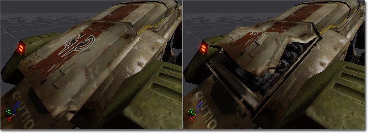 Importing morph targets was covered in the Vehicle Import and Setup section.
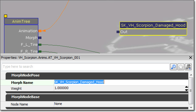
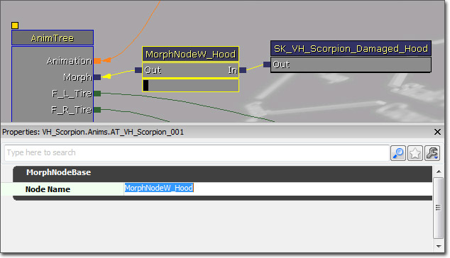
Once you have the vehicle's morph targets imported and ready to go, they must be set up in the AnimTree. First, a MorphNodePose must be created for each morph target. The Morph Name property of this node is what determines which morph target it controls.
Importing morph targets was covered in the Vehicle Import and Setup section.
Once you have the vehicle's morph targets imported and ready to go, they must be set up in the AnimTree. First, a MorphNodePose must be created for each morph target. The Morph Name property of this node is what determines which morph target it controls.
 Next, a MorphNodeWeight must be added. This node controls how much of the MorphNodePose's morph target is blended in at any time. The MorphNodePose should connect to the MorphNodeWeight which in turn should connect to the Morph link on the base AnimTreenode. Make sure to give the MorphNodeWeight a name using the NodeName property as this is how it will be referenced in the scripts by your programmer.
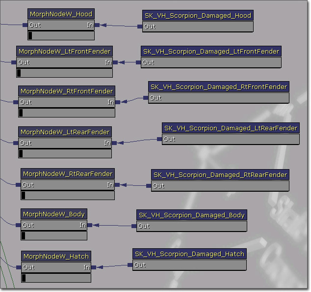
 This process must be done for each morph target used in the damage system.
Damage Nodes
Skeletal controllers can be used with the damage system to cause parts to break off as they get damaged as well as explode when the vehicle is destroyed. The basic damage controller is the UTSkelControl_Damage. This node is mainly used for spawning broken vehicle parts when the vehicle dies, but can also be used for breaking pieces off the vehicle as it becomes more and more dmamaged. The UTSkelControl_DamageHinge and UTSkelControl_DamageSpring nodes are mainly used for breaking pieces off the vehicle as it becomes more damaged. They also add the ability to have the associated vehicle parts become more flappy or looser (depending ont he type of node used, hinge or spring) until they break off. The node gets linked to a specifc bone and damage caused in the location of that bone (or closer to it than any other bone) will be applied to the associated damage controller.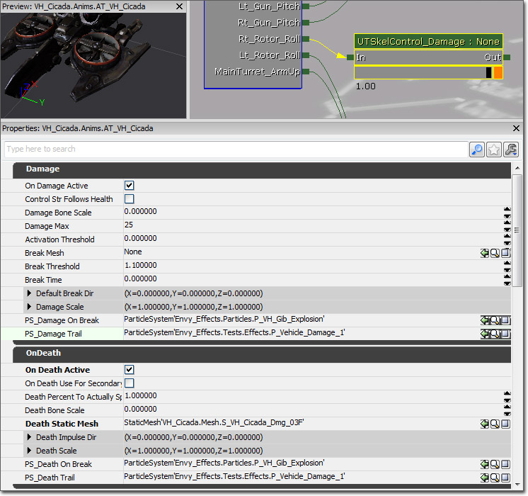 There are many properties common to the UTSkelControl_Damage, UTSkelControl_DamageHinge, and UTSkelControl_DamageSpring nodes:
Damage
There are many properties common to the UTSkelControl_Damage, UTSkelControl_DamageHinge, and UTSkelControl_DamageSpring nodes:
Damage
- On Damage Active - If true, the damage and breaking functionality is enabled for this control.
- Control Str Follows Health - If true, the control strength once active is determined by the current health of the controller. Otherwise it is always full strength once active.
- Damage Bone Scale - The scale to set the associated bone too when the controller breaks apart. Usually (0,0,0) to hide the part completely.
- Damage Max - The amount of damage the controller can take before it is considered dead; essentially, this is the maximum health of the controller.
- Activation Threshold - The health ratio (current health / maximum health) below which the controller becomes active.
- Break Mesh - The StaticMesh to spawn when this controller breaks.
- Break Threshold - The control strength above which the controller looks the begin breaking.
- Break Time - The amount of time it takes to go from breaking to completely broken.
- Default Break Dir - The direction used to determine the velocity of the broken off piece.
- Damage Scale - The scale to be used for the spawned vehicle part. Useful for mirroring the same StaticMesh when being used for multiple parts on opposite sides of the vehicle.
- PS_Damage On Break - The ParticleSystem to spawn when the controller breaks apart, e.g. a small explosion effect.
- PS_Damage Trail - The ParticleSystem to attach to the broken off part as a trail, e.g. a smoke trail effect.
- On Death Active - If true, the death breaking functionality is enabled for this control.
- On Death Use For Secondary Explosion - If true, this damage control is used for the secondary death explosion of the vehicle instead of the primary death.
- Death Percent To Actually Spawn - The percent chance (0 to 1) that this control will actually spawn a broken off part when the vehicle dies.
- Death Bone Scale - The scale to set the associated bone too when the controller breaks apart. Usually (0,0,0) to hide the part completely.
- Death Static Mesh - The StaticMesh to spawn when this controller breaks.
- Death Impulse Dir - The direction used to determine the velocity of the broken off piece.
- Death Scale - The scale to be used for the spawned vehicle part. Useful for mirroring the same StaticMesh when being used for multiple parts on opposite sides of the vehicle.
- PS_Death On Break - The ParticleSystem to spawn when the controller breaks apart on death, e.g. a small explosion effect.
- PS_Death Trail - The ParticleSystem to attach to the broken off part as a trail, e.g. a smoke trail effect.
Setting Up Sockets
Sockets were mentioned previously as being used as attachment points for player cameras and weapon muzzle flashes as well as any additional effects the vehicle may require. Sockets are essentially locators parented to a specific bone which can named and then be offset and given their own individual rotation. This provides an easy way to attach or spawn items at specific locations. Sockets are added to a skeletal mesh inside of UnrealEd through the AnimSet Editor. Press the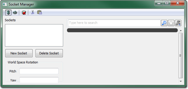 The
The 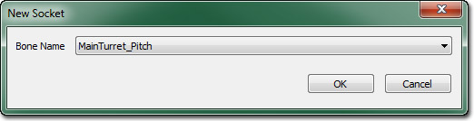 Select the bone that was added at the tip of the barrel of the mesh and then press OK. This will bring up another dialog where the new socket can be given a name that will be used to identify it in code.
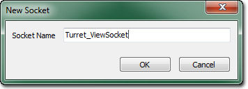 Once you've entered a name, press OK to add the new socket. It should appear in the Preview Pane of the AnimSet Editor and in the socket list of the Socket Manager.
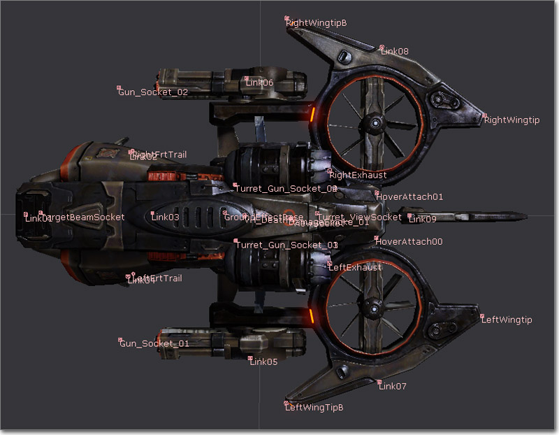
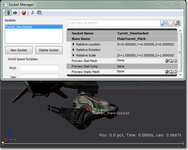 The example shown would be used asa locator for attaching a camera for the passenger controlling the turret. Other sockets would also be added at the ends of each of the weapon barrels and in any other locations where effects might need to be attached. The example vehicle below has had all the necessary sockets added.
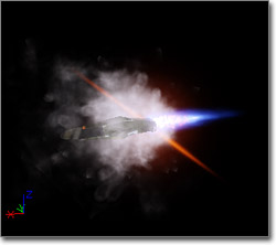
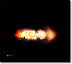
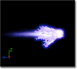
Creating Projectiles
A projectile is the physical representation of the weapon fire. The visual component of Projectiles in Unreal are simply particle systems. Creating particle sytems for projectiles is a straightforward process similar to making any other particle system. Essentially, you want to set up a particle system that recreates how you want to the projectile to appear while in flight. The particle system can be made up of as many emitters as necessary to get the desired effect. Some examples of projectile particle systems are shown below: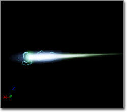
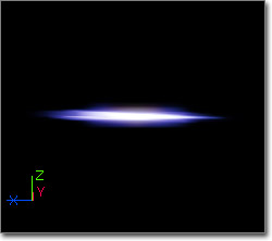
Setting Up Muzzle Flashes
Muzzle flashes are used to simulate the projectile being expelled from the barrel of the weapon, like the flash you would see when a gun is fired in real life. The weapon system in Unreal uses a particle system as the visual component of a muzzle flash. As with projectiles, the particle system for a muzzle flash can be made up of as many emitters as necessary to get the desired look. Some examples of muzzle flash particle systems are shown below: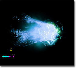
For Programmers
- The name of the SkeletalMesh.
- The name of the PhysicsAsset.
- The name of the AnimTree.
- The name of each wheel bone.
- The name of each SkelControlWheel.
- The radius of each wheel.
Creating The Script File
Below is an example of how you would enter all of the needed information into an UnrealScript class (.uc) file for your vehicle:
// Saved as MyVehicle.uc
class MyVehicle extends SVehicle;

defaultproperties
{

   Begin Object Name=SVehicleMesh
      SkeletalMesh=SkeletalMesh'VehiclePackage.VehicleMesh'
      AnimTreeTemplate=AnimTree'VehiclePackage.VehicleAnimTree'
      PhysicsAsset=PhysicsAsset'VehiclePackage.VehiclePhysAsset'
   End Object

   Begin Object Class=SVehicleWheel Name=RRWheel
      BoneName="R_R_Tire"
      SkelControlName="R_R_Tire_Cont"
      WheelRadius=25
   End Object
   Wheels(0)=RRWheel
}
Performance: Tuning Vehicles
There are many parameters which control how a vehicle handles. Some are per-wheel parameters which reside in each SVehicleWheel object, whereas those that affect the entire vehicle are in the SVehicle and SVehicleSim objects. An explanation of each parameters is available on the Vehicles Technical Guide page.Useful Console Commands
One feature of the Unreal Engine which is very useful for tuning vehicles is theeditactor console command. While driving the vehicle you can type editactor class=svehicle at the console, and a property window should pop up. This allows you to tune almost all of the parameters as you drive around, making iteration very quick.